Removal of surface waters. Diversion of surface and ground waters
A clean and dry yard after rain, no puddles on the lawn and no washed-out beds, healthy plants and perfectly smooth paths are the result of competent planning and installation of surface drainage. It is difficult to achieve such a result on your own without impressive expenses, but it is realistic if you make storm drainage with your own hands to drain the surface and remove rainwater. In combination with a storm drain (a system for draining water from the roof), the drainage network will also reduce the amount of moisture penetrating into the deep layers of the soil - the load on the deep foundation drainage network will decrease.
It is worth planning the layout of drainage networks and storm water even before the start of construction. Foundation protection in the form of a wall system is easier to install if the foundation pit is not filled up. While the construction is going on and there is equipment on the site, it is advisable to order the digging of trenches so as not to dig manually and not to carry dirt in the improved area. Protection against melt and rain water is:

Stormwater and drainage around the perimeter of the house
- Surface linear storm drainage - collection and drainage of rainwater from the ground surface.
- Storm sewer - drainage of water flowing down drainpipes.
- Point drainage - drainage of local areas with problematic natural outflow.

Scheme for removing moisture from the surface: drainage system
Storm sewer network
The storm sewer network is equipped with an outlet to a common highway, if there is a sewer or city stormwater pipe nearby. In the case when the branches of the city network are located at a great distance, the output of the local drainage system and storm sewer is organized in 2 ways: to the filtration field (a section covered with crushed stone to drain moisture into the ground), or to a receiving tank (drainage well, pond, roadside ditch) . Draining from a private storm drain into the public domestic sewer system is prohibited.
System elements:
- Drainage gutters that are mounted along the edge of the roof slopes.
- Water pipes.
- Water intake tanks.

Receiving tank with outlet
- External sewer pipes that are connected to water intake tanks.
The containers are mounted under the outlet of the drainpipe, the pipe is connected to the sewer pipe. Pipes are dug in at an angle to the drain.
Drainage: features of a surface storm system
The drainage system of the surface of the site consists of point and linear branch branches connected into one network with an outlet to the water intake. Storm drainage on the site is equipped in the form of open channels, dug under a slope to the drain site. Marking is performed only after studying the direction of natural outflow during heavy rain. Be sure to form drainage lines:

Drainage network: point catchers and storm trenches
- Along the perimeter of the site.
- On slopes and on sites in natural depressions.

Drainage branches on the slope
- Around the tracks.
Storm drainage around the house is a line of trenches laid along the blind area around the entire perimeter of the buildings. To drain the tiled yard, channels are formed at the entrance to the garage, near the porch, steps.

Point drainage outlets are dug in in places where there is no need to lay drainage channels: under watering taps, near the outlet of downpipes (in areas where there is no storm sewer). Drainage from point drainage wells is discharged into the outlet pipe of the general surface network.
Integration: is it possible to combine storm water with a drainage network

Two separate networks: drainage and storm water
The optimal scheme for draining the site with the house is separate drainage and stormwater networks around the house. It is undesirable to connect linear channels with sewers: during heavy rains or rapid snow melting, one pipe may not be able to cope and overflow through water inlets will occur.
It is advisable to connect stormwater and drainage in one trench only in one case: if the trench is dug under the outlet from the point drainage and sewer rather than perforated pipes are used. The pipes are laid parallel along the bottom of the concreted trench. Lay hermetic sewer pipe it is impossible to enter a channel with drainage backfill: the diameter of the pipe will reduce the usable volume of the ditch and create difficulties in cleaning the trench.

General outlet of point drainage and storm water to the filtration tunnel
Instead of trying to connect stormwater and linear drainage in one pipe, it is better to make a common receiver, especially if you cannot make a tie-in into a city highway. Rainwater can be used to irrigate or fill artificial reservoirs. Plastic tanks are installed as a receiver, or wells are made without a bottom - to drain the incoming liquid into the ground.
How to make storm drainage of the site and around a country house
Storm drainage is a surface system that does not require extensive earthworks and digging deep trenches, so you can do a simple wiring with your own hands. Before starting work, the places of mandatory arrangement of lines and water collection points are determined, and the drainage trajectory is planned. It is possible to detect all places where natural outflow is not enough during heavy rainfall and after the snow melts. It also requires the installation of a branched linear storm drainage area with clayey, moisture-saturated soil that does not absorb water from the surface.
For preliminary calculations of the quantity necessary materials it is worth drawing a diagram of the channels on the site plan.

Storm drain installation plan
Materials: what you need to install a storm drainage network
List of materials needed for independent device storm drainage of the site and installation of the system around the perimeter of the house:
- Trays (gutters) for installation around the foundation. Production materials - plastic, polymer concrete mix, concrete. Plastic channels are installed in areas where there is minimal physical impact on the gratings: along the edges of the lawn, in flower beds. Concrete gutters are strong and durable. Such a tray can withstand loads up to 25 tons. They are installed in places of increased loads: in yards where there is constant traffic, on access roads. Protective gratings are also chosen: metal and cast iron - for areas with heavy traffic, decorative plastic - for the lawn, garden.

- Connecting elements, spacers, bases. Auxiliary materials that the manufacturer recommends using when assembling channels. Be sure to install spacers inside the plastic trays.
- Sand traps. Separately, they buy products for installation in a linear system and for installation in storm water inlets.

On the walls - preparation for pipe removal
- Storm water inlets. Predominantly ready-made plastic containers are used. The outer walls are equipped with preparation for connection with a branch. Plastic receivers are easy to install on top of each other - you can assemble a container of any height.

Containers with basket and attachments
- Geotextile. Cloth for drainage filling channels not equipped with gutters.

Synthetic waterproof fabric
- Crushed stone, sand. The crushed stone fraction is medium and large.
- Mortar for pouring the base under the gutters and water inlets.
- Drainage wells. Ready-made plastic or corrugated pipe of large diameter.

Factory PVC drainage wells
- Pipes for outdoor sewerage with fittings.
- Construction tool. You will need draft boards for formwork in the channels, pegs and line for marking, shovels, picks, building level.
Installation of point water inlets
Point water inlets - stormwater and drainage elements installed under the outlet of drains. It is necessary to plan the installation so that the flow from the drain falls exactly in the center of the grate.

The edge of the well should be flush with the decorative coating
The dimensions of the pit for installing the container are determined by the height of the receiver, adding up to 30 - 40 cm for bedding and base. There should be a gap of up to 5 cm along the perimeter on each side. Dig a recess, level the walls and bottom. Be sure to check the horizontality of the bottom and the angle so that the container does not move during installation.

Checking horizontal level
A dense ten-centimeter layer of compacted sand is formed at the bottom. A layer of crushed stone up to 25 cm high is laid on a sand cushion. It is advisable to fill the bottom with concrete mortar. The poured base is left for several days until it hardens completely, or the container is fixed in a fresh solution (if necessary, fixed fixation).

On the concrete base install the storm water inlet so that the lid of the container is flush with the blind area. If installation is carried out before laying decorative coating, then leave the free edge of the well above the ground to the height of a tile or stone.

Correct installation receiver
Side gaps are covered with rubble or poured with concrete. Before backfilling, a pipe outlet fitting is connected to the outlet. Install internal parts: basket, partitions, fix the lid.
Arrangement of an open storm system around the foundation
Drainage of storm water along the perimeter of the building can be planned as a ring closed at the collection point, without revision wells. For cleaning, collapsible sand traps are provided. Rules for the device of a linear system:
- The indent from the edge of the foundation should be from 50 cm. Optimally, plan the channels along the edge of the tracks or blind area.

Trays - along the edge of the blind area with a margin of height for paving slabs
- The depth of the channels is determined by the height of the tray with a decorative cover with the addition of the height of the bulk layer - up to 40 cm.
- Width - up to 50 cm.
To prevent the installed gutters from shifting and deforming over time, you need to follow a few rules during earthworks. The bottom, the walls should be even and solid. At the bottom, a standard sand cushion and crushed stone bedding are necessarily made.

Plastic tray installed on the factory stand
So that the tray (especially plastic) does not deform, it is better to make a concrete base for installation. The thickness of the concrete layer is 5 cm.

Laying the gutter on the mortar
Gutters are installed in prepared trenches. The structures are interconnected with special locks. The extreme points (at the beginning and at the end of the line) are closed with plastic or metal plugs. If plastic gutters are used, factory spacers are installed inside.

Sand trap in the drain line
The gaps between the trays and the walls of the trench are covered with rubble, or concreted. On long sections, sand traps are installed - in-depth trays with a mechanical filter. At the installation sites, outlet pipes are connected to the sand traps. Trenches for discharge pipes are dug at an angle.
Budgetary storm drainage of the site: building open channels
Drain rainwater from garden paths, flower beds and along the fence can also be done in an economical open way. Instead of ready-made trays, storm drainage filling channels are equipped. Trenches are dug along the planned lines. Depth - from 50 cm, width - from 50 - 60 cm.

Instead of gutters - backfill trench
The branch is formed with a slope towards the receiving tank. The walls are at an angle to the bottom to reduce the pressure of flowing water. The bottom is filled with sand. Check the correct slope. For one meter - up to 3 cm height difference.

Pipe in crushed stone backfill
Geotextiles are laid on the sand layer. The edges are left free. Over the entire width of the trench, crushed stone is covered with a layer of up to 30 cm. A system with a perforated drainage pipe inside the crushed stone backfill will be more durable. Wrap the edges of the canvas with an overlap.

Dry stream with decorative backfill - a beautiful drainage line
Top drainage clip fall asleep decorative material: river pebbles, colorful chips, stone. Dry streams are an aesthetic and economical solution.
Drainage well and drain outlet
The drainage well is the connection point of the system. With a moderate amount of water and good water-absorbing characteristics of the soil, the drainage tank is installed on a crushed stone pillow. Through a well without a bottom, water penetrates the soil.

Drainage well with filling bottom
If the installation of a filter well is not possible, then liquid is drained from the drainage tank into a common storm main or taken out of the site - into a natural reservoir, moat. The outlet from the well can be connected to a pond or a receiving tank dug in the area.
Video: installation of stormwater around the house
Stormwater and linear open drainage are only the surface part of the foundation protection. Along the perimeter of buildings at different depths, it is necessary to create 3-4 types of drainage systems. The choice of the method of organizing and technical parameters of networks depends on the composition of the soil, the depth of the foundation. Doing deep drainage networks on your own is not worth it. Calculations should be done by specialists, and the installation of trench branches is best done immediately after pouring the foundation. Even before the start of construction, a reservoir deep drainage system is being equipped. Not only the ability of the system to drain water in large quantities, but also the durability of the foundation depends on the accuracy of the calculations.
The layout of building plots and other needs must be carried out taking into account the effective removal of precipitation using a drainage system, storm channels and drainage systems. If rain or melt water stagnates, this will contribute to the destruction of the coating and other negative consequences.
Why are surface waters dangerous?
Surface waters are formed from precipitation: snow, rain, hail, etc. This moisture can cause trouble at the site (construction, summer cottage), starting from elementary stagnation of water with bad smell and ending with a violation of the integrity of the foundations near the underlying buildings. The troubles do not end there, also dampness can penetrate buildings and provoke the spread of fungus, an increase in humidity. There is also a danger for sidewalks and road surfaces: cracking, heavy icing, subsidence of the canvas. The root system of plants from excess rainfall can rot, the fertile layer will be washed out, and violation of the thermal regime will create conditions for the expansion of moss and mold.
In order to avoid all these negative phenomena, an excellent removal system is needed. surface water.
This system is of two types:
- point;
- linear.
Also, branches are divided into open and closed. The second option is more used to remove precipitation from entire city blocks. Point is the simplest, it is most often used with a small amount of falling moisture, which is collected in local modules (for example, water flowing from roofs). The linear system is more complex and consists of many elements: gutters, trays, ditches, wells, etc. Moisture is quickly collected from a large area and immediately sent to the central catchment collector.
materials
Concrete, plastic and earth embankments, ditches and trenches are used as materials as a temporary solution to the problem with precipitation. The elements of the surface water drainage system are installed at an angle, which contributes to the rapid collection and discharge of unnecessary moisture. If the site has high humidity through groundwater, then the drainage system is designed comprehensively, taking into account atmospheric phenomena and the influence of underground sources. Often, sand, dirt, debris can get into the drainage channels and trays with water, and therefore special traps are installed. 
These devices do not allow the system to become clogged and cease to perform its direct functions. When drawing up a general project for the removal of surface water, a number of factors must be taken into account: the amount of precipitation, the territory of the site, the presence of groundwater, the level of humidity, the slope.
Since we are talking about arranging a drainage system, it means that our house is already standing (designed) and we are moving on to landscaping or landscape design. I am sincerely happy for you, Lord! Exactly how glad I am to the fact that you are interested in the question: "How to optimally implement water drainage from the site and from the house?". Having dealt with this, you will save a lot of time and money.
To begin with, water drainage is a complex task and should include complementary systems:
- Roof drainage system.
- Surface drainage system.
- In case the level ground water(UGV) on the site is high, and the house has, for example, a basement or an underground garage, there is a need to arrange a deep drainage system to drain groundwater.
The first two systems provide for the removal of rainwater (to eliminate the negative impact of precipitation), the removal of melt water (melting snow) and, accordingly, prevent the appearance of the so-called. "overheads". Verkhovodka, along with groundwater, is a type of soil water, has a seasonal character and appears as a result of precipitation, snow melting, excessive watering, etc. As a rule, by the middle of summer it disappears altogether and can appear briefly only after heavy rains.
Verkhovodka is an unpleasant problem for houses with a foundation (basement), and is also the reason for the rapid filling of a leaky septic tank (cesspool) in the spring and during heavy rainfall.
The task of the roof drainage system is to collect all the rainwater from the roof of buildings and bring it to the right catchment points. If you save on roof drains, the rains will gradually break your paths, blind area, steps and will splash the foundation of the building with an even layer of dirt to a height of up to 50 cm.
Well, if your basement is flooded, its walls are saturated with moisture, and the septic tank needs to be pumped out every 7-10 days, you cannot do without deep drainage.
- What is the soil structure and groundwater level (hereinafter GWL) in your area? The answer to this question will clarify the need for underground (deep) drainage and basement waterproofing, if any. The carriers of this mysterious knowledge are usually the same people who drilled your well for water or specialized geodetic organizations.
- Where will it be done diversion of surface and ground waters? This answer will help you figure out the point of water discharge (it can be one for both surface and groundwater) and simplify the preparation of a technical solution. I am familiar with the following options:
- Storm sewer. As a rule, this is a concrete pipe of large diameter. Ideally, it is buried below the freezing depth of the soil and equipped with collectors, i.e. connection points for individual stormwater drainage systems, for example, from your site. Storm water is drained into natural reservoirs.
- Mixed sewer. Disposes superficial and, actually, sewer drains. Also equipped with collectors. Provides for the arrangement of wastewater treatment systems before they are discharged, for example, into water bodies.
- Drainage field (infiltration system). Equipped in case of absence of the options indicated above. A system that provides a uniform and natural "absorption" of storm water into the ground directly at the site of their collection.
- Neighborhood :). The simplest and fast way, which also allows you to "get closer" to your neighbors in the shortest possible time.
- Will the water be drained by gravity or will a drainage well and pump be needed? To do this, you need to answer the previous questions, as well as determine the slopes of the site. The discharge point should be provided at the lowest part of the site.
- What is the area of the catchment area? The throughput and, accordingly, the cost of water collection systems depends on this. Knowing the area of your site, you can independently calculate the estimated flow of rainwater, which should be removed by drainage systems. Use the program for this.
- What load (surface pressure) must withstand engineering structures for water drainage? Let me rephrase. Who will walk (ride) on them? The so-called. load class and all the same cost. The load class is important for both deep and surface drainage.
If your site is located on a slope and you want to drain surface water flowing from the upstream site, then to intercept water, you should provide a system of drainage trays perpendicular to the slope in the upper part of the site (then the site looks landscaped and has flat surface) or dig a drainage ditch along the upper boundary of the site and connect it to the side ditches (the site becomes like a medieval outpost).
After you have answered the preparatory theoretical questions, should be taken for implementation. I strongly recommend to develop a project or just a technical solution. To do this, either contact design organization(Department of water disposal and sewerage), or draw a sketch yourself .... and find an imperturbable builder who will undertake to bring it to life.
Ask and delve into the details! Builders in most cases install a gutter system to drain water from the roof, but they do not consider it necessary to divert this water far from the foundation. I know of cases when a contractor installed storm water inlets, but "discharged" the collected water through the bottom of the same storm water inlets into the ground near the foundation. In this case, there is no fundamental difference between if the water simply drains from the roof and wets the foundation, or flows through the drainage system (collects in a storm water inlet) and ... wets the foundation. The soil adjacent to the foundation, after construction works usually looser than naturally formed soil, so rain water accumulate in the sinuses and penetrate into the concrete. In winter, water freezes and destroys concrete structures.
Therefore, in addition to arranging a blind area around the house with a width of 80-100 cm, the water collected by the drainage system must be diverted to the storm sewer. This can be done with a system of drainage trays (Fig. 1) or a device with point storm water inlets (Fig. 2).
In the first case, we have less earthwork, the system will always be available for inspection and repair. In the second case, we can lay the pipe from the storm water inlets in the same trench with the drainage pipe.
In this case, in no case should the surface drainage system be connected to the drainage of the base of the house. Otherwise, rainwater will fall into the drainage and vice versa - wet the foundation!!!
From above, sand traps and drainage channels are closed with removable protective and decorative gratings that prevent debris, leaves from entering the system and do not impede the movement of pedestrians and vehicles. The linear drainage system is connected to the storm sewer through a system of vertical and horizontal outlets.
Important!!! When installing a surface drainage system, slopes (minimum 0.005, i.e. 5 mm per meter of length) must be provided for the movement of water by gravity! This can be done in two ways:
- By using the slope of the surface.
- Due to the use of channels, which have an inner surface with a slope (this function is provided in the concrete channels of some manufacturers: Standartpark, Hauraton, ACO), as well as due to a stepped slope organized using channels of different heights.
The arrangement of an underground drainage system is most appropriate to combine with foundation work- it won't cost much. If, during the operation of the house, it turns out that the groundwater level is very high, and the drainage of water from the house is not organized, this will cost you a pretty penny.
underground drainage- this is a system of drainage pipes (drains, i.e. pipes with holes, covered with rubble and wrapped in geotextiles) and drainage wells. Geotextile protects drains from silting.
Drainage wells are designed for Maintenance drainage system, such as water jet cleaning. A drainage well is provided at every second bend of the pipe, so that both the inlet and outlet sections of the pipes can be serviced through it.
The wells are assembled from concrete rings diameter 400 mm and 700 mm. Recently, ready-made plastic wells with a diameter of 315 mm are increasingly used.
The water collected by the drainage pipes enters the collector well (water collected by the surface drainage can also be supplied here), equipped with a check valve that prevents water from the well from flowing back into the drainage system. From a common well, water is removed (for example, pumped out) into a communal storm sewer, an open drain, or it is absorbed into the soil through a specially poured layer of rubble (drainage field).
Well, in general, it’s enough for the first time (especially if you don’t have special education). Conclusion: The arrangement of surface, and if necessary, deep drainage is a feasible task, but ... if in doubt, entrust it to professionals. If you are going to secure basements, foundations, etc., and are faced with perched water (groundwater), then due to the complexity and complexity of the task, I advise you to choose one contractor who will be responsible for the development and installation of the entire system as a whole. This is important because individual works, performed by different contractors, as a rule, do not solve the problem as a whole, and the contractor always has the opportunity to say: “It's not me!”. Try to negotiate a warranty on drainage systems for at least a year. Only a full season will prove their viability!
Since you are paying money, do not entrust such a difficult task, for example, to tilers who pave paths for you! They can be performers - but they must be led by a professional.
Vladimir Polevoy.
Lecture on the topic: Engineering organization of the territory of populated areas.
Part 11: Organization of surface water runoff.
Organization of surface water runoff
The organization of the runoff of surface (storm and melt) water is directly related to the vertical planning of the territory. The organization of surface runoff is carried out with the help of a general drainage system, which is designed in such a way as to collect all the runoff of surface water from the territory and divert it to places of possible discharge or to treatment facilities, while preventing flooding of streets, low places and basements of buildings and structures.

Rice. 19. Schemes of surface runoff organization depending on the relief of the territory.
The main parameters characterizing rains are intensity, duration and frequency of rains.
When designing rainwater drainage, rainwater is taken into account, which gives the highest flow rates. That. for calculations, the average rain intensity for the periods is taken different duration.
All calculations are carried out according to the recommendations:
SNiP 23-01-99* Climatology and geophysics.
SNiP 2.04.03-85 Sewerage. Outdoor networks and facilities
The organization of surface drainage is carried out from all urban areas. For this purpose, open and closed gutter system cities that discharge surface runoff outside the urban area or to wastewater treatment plants.
Rain network types (closed, open)
open network is a system of trays and ditches included in the cross profile of the streets, supplemented by other drainage, artificial and natural elements.
Closed- includes supply elements (street trays), an underground network of pipes (collectors), rain and manholes, as well as special-purpose units (outlets, water wells, overflow wells, etc.).
A mixed network has elements of an open and closed network.
closed rain network
Rainwater wells are installed to ensure complete interception of rainwater in places where the design relief is lowered, at the exits from blocks, in front of intersections, from the side of the inflow of water, always outside the pedestrian lane (Fig. 20).
On the territory of residential development, rainwater wells are located at a distance of 150-300m from the watershed line.
On highways, storm water wells are placed depending on the longitudinal slopes (Table 4).

Rice. 20 Scheme of placement of storm water wells at intersections
.

Rice. 21. The location of storm water wells in terms of the highway.
1 - collector, 2 - drain branch, 3 - rainwater well, 4 - manhole.
The storm (rain) collector, located along the highway, is duplicated if the width of the carriageway of the highway exceeds 21 m or if the width of the highway in the red lines is more than 50 m (Fig. 21, c). In all other cases, the circuits shown in Fig. 21, a, b.
For ease of operation, the length of the storm sewer branch is limited to 40 m. It can have 2 storm water wells, at the junction of which a manhole is installed, however, in areas with a large volume of flow, the number of storm water wells can be increased (up to 3 at one point). With a branch length of up to 15 m and a sewage flow rate of at least 1 m / s, connection without a manhole is allowed. The diameter of the branches is taken within 200-300 mm. Recommended slope - 2-5%, but not less than 0.5%
If necessary, storm water wells are made combined: for receiving water from the roadway and for receiving water from drainage systems (drains).
Inspection wells are located in places where the direction of the route, the diameter and slope of pipes change, pipeline connections and intersections with underground networks at the same level, in accordance with the terrain conditions (slopes), the volume of flow and the nature of the laid storm sewer collectors, on the storm (sewer) network.
On straight sections of the route, the spacing of manholes depends on the diameter of the drainpipes. The larger the diameter, the greater the distance between the wells. With a diameter of 0.2 ÷ 0.45 m, the distance between the wells should be no more than 50 m, and with a diameter of more than 2 m - a distance of 250 -300 m.
The storm collector, as an element of the storm sewer, is located on the built-up area of the city, depending on the overall layout of the entire storm network.
Storm sewer depth
depends on the geological conditions of the soil and the depth of freezing. If the soil does not freeze in the construction area, then the minimum depth of the drain is 0.7 m. Determination of the depth of laying is carried out in accordance with the requirements of the SNiP norms.
An ordinary drainage network is designed with a longitudinal slope of 50/00, but in flat terrain it is reduced to 40/00.
In flat areas, a minimum collector slope of 40/00 is accepted. Such a slope ensures the continuity of the movement (constancy) of storm water in the collector and prevents its silting.
The maximum slope of the collector is taken such that the speed of water movement is 7 m/s, and for metal collectors 10 m/s.
At large slopes, the collectors may fail due to the occurrence of water hammer.
Among the possible structures on the drainage network are overflow wells, arranged in areas with a large fall in relief, to reduce the speed of water movement in the collector, which exceeds the highest allowable norms. With significant extreme slopes of the terrain, fast currents, water wells are arranged on the collector route, or cast iron or steel pipes.
For sanitary reasons, it is advisable to arrange outlets of the drainage network outside the boundaries of the city's development into treatment facilities (sumps, filtration fields).
Open rain network
stands from the street and intra-quarter. In the network, ditches and trays are distinguished that remove water from low areas of the territory, bypass trays that remove water from low areas of the territory, and ditches that divert water from large areas of the basin. Sometimes the open network is complemented by small riverbeds and canals.
The dimensions of the cross sections of individual elements of the network are determined by calculation. With small runoff areas, the cross-sectional dimensions of trays and cuvettes are not calculated, but are taken for design reasons, taking into account standard dimensions. In urban conditions, drainage elements are strengthened along the entire bottom or around the entire perimeter. The steepness of the slopes of ditches and channels (the ratio of the height of the slope to its inception) is set in the range from 1:0.25 to 1:0.5.
Trays and ditches are designed along the streets. The routes of drainage channels are laid, as close as possible to the relief, if possible outside the building boundaries.
Transverse section ditches and trays are designed rectangular, trapezoidal and parabolic, ditches - rectangular and trapezoidal. The greatest height of ditches and ditches is limited in urban areas. It is made no more than 1.2 m (1.0 m - the maximum depth of the flow, 0.2 m - the smallest excess of the edge of the cuvette or ditch above the flow).
The smallest slopes of carriageway trays, ditches and drainage ditches are accepted depending on the type of coating. These slopes provide the lowest non-silting speed of rainwater movement (at least 0.4 - 0.6 m/s).
In areas of the territory where the slopes of the relief are greater than those at which maximum current velocities occur, special structures, fast currents, and stepped drops are designed.

Design features of the rain network during reconstruction.
The position of the network in plan and profile is determined by the specific design conditions, as well as the height and planning solution of the territory.
If the existing collector cannot cope with the estimated costs, the drainage network will be reconstructed. The design solution in this case is chosen, taking into account the reduction in the catchment area and the estimated water flow, due to the laying of new collectors. Laying additional pipelines is carried out at the same elevations as the existing network or at deeper elevations (if the existing network is not deep enough). Pipes of insufficient section are partially replaced by new ones with a large section.
In areas of the existing network that have a small foundation, they provide for strengthening the strength of the structure of the drain and its individual elements, and, if necessary, thermal protection. Continuation of the lecture on the topic: Engineering organization of the territory of populated areas.
Part 1: Vertical planning of urban areas.
Part 2:
Let's be honest: most of us would not like to have land plot with great flair. This is understandable - the unknown is scary. Let's put everything on the shelves together, and only then draw conclusions.
Possibilities and disadvantages of a plot with a slope
First of all, let's consider the possible troubles:
- the choice of the location of both the house itself and the buildings is noticeably limited;
- there are problems with watering, as the water in the soil will linger for a short time;
- movement around the territory is complicated, especially in ice;
- it is difficult to organize a sufficient area for games and entertainment;
- the need to combat landslides and soil erosion;
- a steep slope is a source of increased danger for children;
- unsuccessful orientation of the slope of the site relative to the sun can lead either to excessive or insufficient illumination of the earth's surface;
- the movement of air masses along the slope can lead to drying up of the soil at the top and frosts in the lower part of the slope;
- landscaping a site with a large slope requires increased costs;
- possible difficulties with access roads;
- providing water can be difficult.
Now about the positive aspects of placing a house on a slope:
- you will get a building plot at a lower price, and the increased costs of its arrangement can be partially compensated by your own creative work;
- problems of water disposal are easily solved: the territory of the yard will be dry, it will be possible to equip the basement in the house or the cellar;
- groundwater problems on such lands are rare;
- the hillside always protects the house from the wind from one direction;
- the cost of building the basement floor of a building is noticeably reduced, since all the excess land is easily used for partial leveling of the relief;
- from the windows of a house located high, a wide view opens;
- when placing a site on the south side of the slope, it is possible to increase the insolation of the courtyard, on the contrary, if the site is located on the north side, solar activity will be weakened;
- a site located on the eastern or western slope will have an average illumination;
- apparently the most important thing: the use of a huge list of landscape design techniques (retaining walls, terraces on the slope of the site, alpine slides, winding paths, a pond, a dry stream, special ornamental plants, etc.) will allow you to get a natural, organic and unique design of the allotment of land.
As you can see, the pros and cons gradually flow into tastes and preferences. The following video examines some of the features of the layout of the site with a slope.
Thus, by spending more effort and money on the development of a site with a slope, you get a more interesting and unusual result.
Of course, the degree of significance of the above circumstances is directly related to the magnitude of the ground level difference. To calculate it, it is necessary to divide the difference in heights of the extreme points of the site by the distance between them and convert the result into a percentage. For example, if the maximum height difference is 3.6m, and the distance between the points of the difference is 20m, then the slope will be 3.6: 20 = 0.19, i.e. 19%.
It is believed that a slope of up to 3% is flat terrain, but a site on a steep slope of more than 20% is not suitable for construction.
Features of the placement of buildings on a slope

 Site plan on a slope
 Firstly, it should be noted that the underground and basement of the house on the site with a slope will inevitably have characteristics. This also applies to other buildings. Usually the house is located on the highest and driest place. Thus, the issue of water disposal from the most important object is solved. Toilet, compost pit, the shower should be located below the house and no closer than 15-20m. Recreation area - gazebo, barbecue, etc. it is better to do it on the same level with the house. Buildings, between which the most frequent movement is expected, are best placed on different sides of the site. In this case, the length of the tracks increases, but the slope to be overcome decreases. In the idealistic version, the buildings are placed in a checkerboard pattern. The garage is conveniently identified at the bottom of the allotment. In this case, the garage building can be used as a means of compensating for the steepness of the slope.
Strengthening terraces on a site with a slope
There are two fundamentally different methods for planning an uneven allotment: without changing the landscape or with maximum leveling of the earth's surface. In my opinion, a compromise should be used for all possible methods of leveling the territory, as well as masking ground level differences.
In this case, there is no point in achieving complete alignment of the site.
When planning an inclined surface, several tasks are set: prevention of soil slippage; convenience of using the surface of the earth for recreation and cultivation of fruit crops; ease of movement around the courtyard. First of all, the maximum possible leveling of the relief is carried out by moving the soil. It is quite possible that it will be beneficial to remove part of the land from the allotment or, on the contrary, to bring the missing soil. A reasonable technique is the use of land mined when digging a pit for a basement or cellar. 
 Creating terraces with stones
The second, most common method is terracing, that is, the creation of flat areas located at different heights. The more terraces, the lower their height, which means that the arrangement of the slope is easier. With a terrace height of up to 70 cm, it is possible to create retaining walls. best material- natural stone. For such a design, it is necessary to make a substrate of crushed stone 10-20 cm high. With a low terrace height, the stone can be laid without a binder. However, in such a situation, there is a danger of washing out the soil with water during rain or irrigation. It is more reliable to make a laying of a retaining wall on cement mortar. The use of brick to create terraces is considered inappropriate, since repeated exposure to moisture and low temperatures leads to its rather rapid destruction.
Suitable for terrace heights up to 2 meters reinforced concrete structures: foundation blocks, slabs and monolithic concrete. Often it makes sense to create concrete retaining walls with some slope, with the expectation of the extrusion effect of the soil. AT difficult situations you can not do without a reliable and full-fledged foundation. It makes no sense to additionally finish the retaining walls with decorative tiles or stone on an adhesive or cement basis. Frost and water will quickly ruin your work.

 concrete retaining wall
 Structurally, "ventilated facades" are suitable here. However, in a decorative sense, such a technique is hardly appropriate. It is much easier and more efficient to lay a corrugated surface with a special pattern in the concrete formwork. Subsequently, you can decorate the concrete with durable water-based paints.
It is very effective to use a French invention - gabions - to strengthen the terraces. Gabions are rectangular mesh structures filled with natural stone. Ready-made modules from special durable wire can be purchased or made by yourself. Gabions are not afraid of soil erosion, as they do not have absolute rigidity. They are also resistant to water, as they do not retain it in themselves. When filling gabions with stone and rubble, you can add a certain amount of earth, in this case, greenery will soon sprout, which will disguise the wire and give the retaining wall a natural look.
The simplest method of strengthening a slope is a sloping embankment. It is better to strengthen the embankment from shedding plastic mesh and geogrid. Being planted with a lawn, special grass and shrubs, such an embankment surface will be quite reliable and aesthetic.
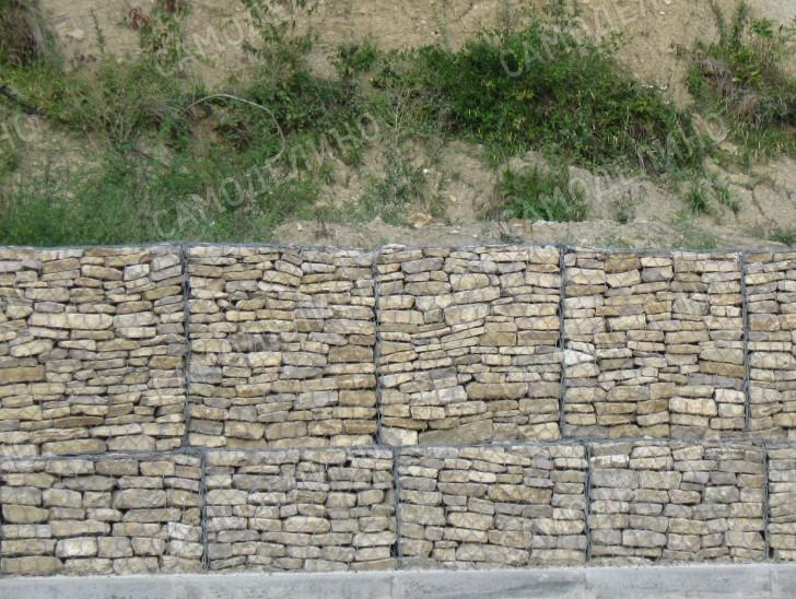
 Gabion retaining wall
 Wastewater - two sides of the coin
It’s good that in a territory with a slope, water will quickly run away both in rain and in flood: it will be dry underfoot. However, rapidly leaving water can take a noticeable part of the soil with it and destroy something. The conclusion is unequivocal: we need to think about how to properly drain on a sloped area.
The scheme seems to be optimal when water is collected from different areas by separate conduits that go beyond the yard. Moreover, each terrace should ideally be equipped with a drainage system.
The simplest solution is laying open concrete trays. The trays are laid on a pre-prepared base: a layer of crushed stone is about 10 cm, a cement-sand mixture (in a ratio of 1 to 10) is about 5 cm. The trays are easily cut and fitted to each other with the help of an angle grinder. Relatively cheap trays have disadvantages: they interfere with walking paths and their cross section is not enough when placed on common drains in the lower part of the site. The last obstacle can be overcome by making the drainage channels yourself from concrete. Pipe sections can be used to form channels suitable diameter. There are also options for closed-type storm drains that are manufactured by industry. The upper part of such drains is closed with special grates for receiving water. Such designs look aesthetically pleasing, do not create obstacles for the movement of people. However, they are noticeably more expensive and more difficult to install. In addition, the problem of insufficient section in the lower part of the steep section remains relevant.
 Drainage with trays
 Another option for drainage is drainage channels. The system is closed and saves space. To organize drainage, trenches with a depth of 0.3-1m are torn off. The bottom of the trench is filled with sand, a layer of 10 cm is enough, it must be rammed. The sand is covered with geofabric, on top of which crushed stone of medium size is poured. The thickness of the crushed stone layer is up to 20 cm. If a small flow of water is expected in this area, then it is enough to cover the crushed stone with geotextile again, and then successively fill it with sand and soil. With a high water flow in the channel, a perforated plastic pipe. The rules for laying pipes are the same as for the arrangement of sewers: a slope of at least 3%; fewer turns and sudden level changes to prevent debris from accumulating in problem areas; secure pipe connection.
Paths and stairs - decoration of the site
It goes without saying that navigating uneven terrain can be difficult and even dangerous. Hence the requirements - to approach the arrangement of all ways of movement of people with special care. Please note that even a relatively flat track with a slope of about 5% can become an insurmountable obstacle during ice. This means that the coating of all paths and stairs should be as rough and ribbed as possible. The steps of the stairs should correspond as much as possible optimal size: tread width 29cm, riser height 17cm. The slope of the stairs cannot exceed 45%. It is better to avoid spans of more than 18 steps and provide rest areas.

 stone staircase
 It is very convenient if the height of the steps of all stairs is the same. It's quite real. For example, when building our own house with our own hands, we managed to ensure the same parameters of steps on both floors of the house, including the basement, as well as on the porch and in the garage. The arrangement of handrails on steep slopes is absolutely necessary, and even on quite gentle sections, handrails will be quite justified.
Materials for arranging paths and stairs can be very different: crushed stone, stone, concrete, wood, artificial turf and plastic gratings. Stairs, separate steps, winding paths - all these attributes should be considered as elements of decoration and individualization of the courtyard area. At the same time, I consider it necessary to recall General requirements: Pathways must not become slippery and dangerous in inclement weather. It may be necessary to provide special handrails for children.
Wonderful landscaping and landscaping opportunities
Alpine landscape design on a site with a slope can be called a pleasant necessity. It is based on natural stones, flowers and other plants. All this together and various options application serves to counteract the erosion of the earth on the slope and at the same time is a decoration. Since water does not retain well on a slope, plants may need frequent watering. Thus, for garden beds and fruit trees it is necessary to highlight the best areas: well-lit, protected from the wind. Sloping garden beds located at the base of a slope may be exposed to cumulative cold air.

 Strengthening the slope with plants
 Ideally, the entire area should be planted with various plants. On the slopes, unpretentious creeping plants are used that do not require much moisture and have a branched root system. Different climatic regions may have their own preferences. Concerning middle lane Russia, the use of shrubs is appropriate here: ivy, barberry, lilac, Japanese quince, elderberry, derain, etc. Coniferous plants will wonderfully decorate the site: juniper, spruce, cedar, pine. Good fit deciduous trees: birch, hazel, willow (in wet places). For arranging rockeries, tenacious, stonecrop, cinquefoil, bells, alpine carnation, sedum, etc. are well suited. The arrangement of lawn areas is quite appropriate.
In order to visually level the terrain, tall plants are planted at the bottom of the slope. Sometimes it becomes necessary to close buildings located on the top of the slope from view, and then the strategy for placing tall and short varieties changes.
A low fence along the retaining wall will cover ugly surfaces and beautify the landscape. It is extremely appropriate to create on a site with a rockery slope. To do this, stones of different sizes and in random order are laid out on the slope. It is interesting to use stones of different composition and texture. Free areas are filled with crushed stone, marble chips, etc. The gaps between the stones are planted with the plants described above. Thus, with your own hands you can create the most unusual and amazing creative compositions. Of course, plants will grow only on soil that is quite suitable for this.
You can decorate a mountain garden with figurines made by yourself, or purchased in a store for summer residents.

 Stream bed made of stones
 The landscape composition "dry stream" was invented in Japan almost specifically for sloping surfaces. The idea is to simulate water with small stones and/or plants. At the site of the future channel, it is necessary to dig a shallow trench of the intended form of the stream. The bottom of the groove is covered with geotextile to protect against weeds. Then drainage is laid in the form of fine gravel, and the channel is covered with soil from above. "Stream" is planted with flowers of blue and blue color or sprinkled with any gravel, preferably blue. Then along the "shores" you can plant flowers. A "dry stream" can exist on its own, or originate from an earthenware jug partially buried in the ground. I wonder if the nearby path will “throw” a small bridge over the “stream”.
On a site with a slope, it is very interesting to use the following technique: a channel for draining water is made in the form of a “dry stream” made of stones. When it rains, the stream will fill with water, which will fall into a small pond at the bottom of the slope. Quite functional and pretty!
Arches on a site with a slope will be very functional in combination with a bridge and stairs. Of course, the arch is worth decorating climbing plants.
After reviewing the above material, you probably already understood: there are a lot of opportunities for decorating a site on a slope! In one of the articles we will talk about a specific example. We wish you creative success in the implementation of your plans. Perhaps the following video will help you.