Homemade soldering station based on Hakko T12. Assembling a soldering station on Hakko T12 tips Which hakko t12 tip is better for smd
Electronic components are sensitive to high temperatures. This means that for each component there is a temperature above which it should not be heated.
Overheating of the component can occur both during operation of the device and during the soldering process. There are many reasons for overheating during operation that are not of interest to us today, since we will talk about soldering and soldering irons.
What is soldering?
Soldering called the method of permanent connection of several parts using a metal with a lower melting point than the connected parts.
When the solder is heated to its melting temperature, it spreads over the surface of the parts to be joined, envelops the protrusions and fills the gaps between them. After the solder cools, a strong bond is formed. Soldering allows you to connect parts from different metals. The main thing is that these metals are wetted with solder.
For example, precious metals, copper, nickel, brass, bronze are well wetted with tin-lead solder, and steel, aluminum, cast iron, and iron are poorly wetted. Therefore, for high-quality soldering, it is necessary to select the right solder.
Solders
Tin-lead and lead-free solders are used in the production of electronics. The obvious disadvantage of tin-lead solders is lead. Lead-free solders do not have lead in their composition, but they did not become less toxic because of this. In addition, lead-free solders suffer from the formation of tin whiskers. So if you still think that ROHS is meant to improve the environment, then it is not. I would suggest that the directive serves to mask the decrease in the lifetime of email. mass production devices.
The solder may additionally include cadmium, bismuth, antimony, zinc, copper. They are included in the composition of the solder in order to give it additional properties. Cadmium to improve anti-corrosion properties. Antimony for gloss. Solders with zinc are used where the soldering surface is exposed to moisture. Etc.
Solders are also divided according to their melting point into fusible and refractory solders. The temperature after which solders are considered refractory is 450 ° C. Among radio amateurs, tin-lead solders POS-40 and POS-60 are most common. The numbers 40 and 60 indicate the percentage of tin in the solder. The lower the number, the higher the melting point of the solder.
Solder fluxes
For high-quality soldering of a component to a printed circuit board track, one solder is not enough, since the soldered surfaces are oxidized, and oxides spoil the soldering quality. To eliminate oxides from the surfaces to be soldered, fluxes are used - substances that remove oxides and fats and improve wettability.
The use of a good flux makes the soldering process easier and improves its quality. Fluxes themselves can be divided into those requiring rinsing after soldering is completed and those that do not require rinsing. Clean-free fluxes are very convenient for use when soldering components that cannot be crawled under. Such as chips in BGA packages
Soldering tools
The main tool is a soldering iron. It is adjustable, non-adjustable, large, small, induction or conventional. To manually mount electronic components, you should use adjustable soldering irons that quickly heat up to a predetermined temperature and maintain it during the soldering process, when the heat from the tip is transferred to the solder, the conductor on the board and the soldered component and it cools down.
Among radio amateurs, clones of Hakko stations are common. They are many times cheaper. Often they also have a blow dryer on board. These stations use a copy of the Type 900M tip. Copies of these stings have a birth injury in the form of an air gap between the heater and the inner surface of the sting. The original sting also has a gap, but it is designed so that during the heating process the gap will disappear due to the thermal expansion of the metal, and this is not taken into account in copies. The result was a bad copy, since the tip heats up for a long time and cools down quickly when soldering massive elements. These complaints will no longer be discussed.
The 900M type tips have been replaced by T12 cartridge tips, which do not have an air gap problem. They are produced in 84 types. I will consider the most interesting and running ones.
How T12 stings work
The peculiarity of such a sting lies in its structure: a capsule, inside of which a temperature sensor is located as close as possible to the tip. The station takes information about the temperature of the tip from the sensor and, using the PID controller, automatically corrects the energy supply to the heating element.
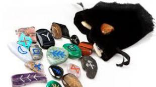
Types of stings T12
The original developer of these stings is the Japanese company Hakko. She produces many interesting instruments. There are more than 30 types of stings in the series alone. One of them is the T12 series, which became widespread due to the fact that the Chinese began to massively rivet these stings and sell them at bargain prices.

The picture above shows examples of T12 tip types. The most popular: BCM / CM, BC / C, B, D, I, J, K. SMD TYPE Quad / Tunnel stings are quite exotic in the life of a radio amateur. Now let's figure out for what purposes which stings are intended.
Type T12-K

 The sting is in the shape of a knife. One of the most versatile blades as it can be used in many different ways and can be worked either with the tip, with the flat part on the left or right side, or with the end. The choice of usage method depends on the soldering conditions.

The cut length is 6.65 mm. With such a sting, you can crawl into narrow gaps between components, solder several component leads at once, tin the PCB pads or wires. T12-K comes with sharpening on the right: T12-K, T12-KR,T12-KRZ; left: T12-KL; bilateral: T12-KF, T12-KFZ, T12-KU. All Chinese stings are actually double-sided sharpening.
Index U in the marking means a reduced diameter of the sting. This lowers its heat capacity. Index Z indicates that the sting has a thicker coating. Such a sting will last longer.
Type T12-BC/C

 BC in the marking means that the sting has the shape of a truncated cone, and FROM designates a sting in the form of a truncated cylinder. The difference between them lies in their heat capacity. At the sting sun she is more.
There are other variations of these stings: BCF/CF and BCM/CM. Sting with index F have a working surface only on a cut, and with an index M have a small notch on the edge of the tip, which allows the tip to hold a drop of solder and soldering will be done with a miniwave. All sting type BC/C come in diameters from 0.8mm to 4.2mm.
Sting type BC/C are designed for soldering heat-intensive components and leads between which there is a sufficient distance so as not to plant snot. Hakko also recommends the use of these tips for soldering chip components, as they allow the formation of a correct solder joint fillet (s older fillet).

Fillet(from German Hohlkehle - groove, notch) - the shape of the surface in the form of a groove, a notch on the outer or inner edge of the part.
When soldering surface mount components, correctly made solder joints have a concave shape, which is provided by the volume of solder and the process of wetting the contact surfaces. This form provides the minimum consumption of solder, as well as the best conditions for uniform solidification with the formation of a strong defect-free joint.
Often, the term "solder joint fillet" refers to the solder joint itself or the volume of solder in the joint.
Type T12-D
 This type of sting looks like a regular flat screwdriver. You can work with such a sting both on the front side and on the end side.
More than 10 subspecies of T-12D are produced with a tip width from 0.5 mm to 1.2 mm. What changes its heat capacity. The tip with a width of 0.5 mm has the smallest heat capacity.
Most of the radio amateurs are accustomed to such stings, since on ordinary soldering irons the stings have a similar shape. Two more versions of such stings are produced: with an extended service life (long life) and high-performance ones with increased heat dissipation (heavy duty).

 The W index is placed on a high-performance sting, the L index indicates that the sting has an elongated tip. For example, T12-DL. Such stings have a heat capacity even more than stings with the W index

I talked about the most popular, in my opinion, stings. I use T12-B2, T-12K tips myself. By the way, when installing in a soldering station, new tips should be calibrated. Many stations allow you to calibrate tips and save a "tip profile" so that when you replace one tip with another, you can switch the profile and not re-calibrate the tip.
What is a sting Hakko T12? This is a cartridge that includes a soldering iron tip, heater and thermocouple. Now gaining popularity and the network is full of articles about them. Due to the fact that they were repeated by the Chinese, the prices for them on Ali are around $ 4, and you can often buy a stock for a piece at a price of around $ 3. The range of these stings is wide, it is claimed that there are more than 80 models. (By the way, T15 are the same stings that are fully compatible with T12)
I was attracted to these stings too after watching the reviews. One of the highlights is fast heating. When you are debugging or repairing, you often need to solder one wire or replace some part, and waiting every time the soldering iron heats up is annoying, and keeping it on all the time, in addition to reducing the resource, does not make the air in the room cleaner. Here, heating is literally in ten seconds, i.e. while he dripped the flux and took the tweezers, the soldering iron is ready. Also not a bad opportunity to warm up large landfills.
Putting it all together the right way with a store-bought quick-change soldering iron handle, etc. for the money it’s not too justified, since a ready-made station like BK950D costs $ 35-40 on AliExpress.
Therefore, I decided to simplify everything as much as possible by refusing to change the stings. In principle, as a rule, only a pair of stings is used in work, rarely three. I decided to just make a couple of soldering irons to get a two-channel soldering station.
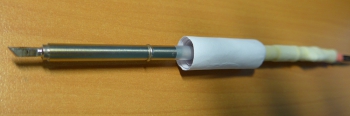
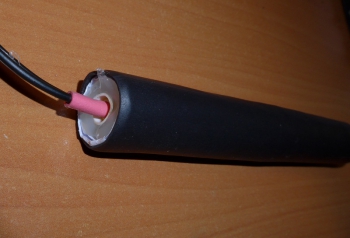
So I bought one T12-KU tip for testing.
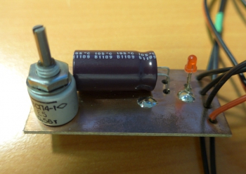
The tip rod at the end has two contact belts, between them a heater with a resistance of 8 ohms and a thermocouple are connected in series. Supply voltage up to 24V and current up to 3A. The maximum power is about 70W.
If you look from the far side of the heater, then first it goes plus then minus and the body of the cartridge itself is the ground and serves to ground the sting.

I fixed the wires to these belts with a simple twist and crimped them with several heat shrinks.

Two thickenings are visible on the sting rod. After the second thickening from the tip of the sting, the rod has a low temperature, and here you can already take it with your hands. In this place I wound paper with ordinary stationery glue.
If there is a ready-made soldering iron handle or a suitable tube, then you can already glue the rod. But since I didn’t have anything at hand, I also glued the pen out of office paper.

Of course, after each layer of paper, the glue must be allowed to dry. After complete drying, I crimped the heat shrink on top to make it less dirty and more pleasant to hold.

At the back, to increase rigidity, I filled it with glue (there is literally not a large ring of glue).
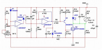
The temperature controller made analog based on a circuit from Chinese regulators. The polarity of the heater is not indicated on the diagram, plus the heater according to the diagram from above, the minus is connected to the ground of the circuit.
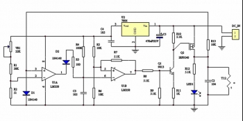
Just redone for existing parts. I replaced the 7806 stabilizer with LM317, Q1 2N2222, Q2 AO4407 and added a protective diode D3. I bring a drawing of a printed circuit board, it is made on a two-sided textolite, the second side is under an earthen polygon. All smd resistors and ceramic capacitors size 0805. Additional shunt capacitors 0.1uF, but you can not install. C4 size B.

The only scarce part in this circuit is the P-Mosfet.
I also tried converting the circuit for N-Mosfet, which are much easier to get or dig out.
WARNING. The circuit does not work when using LM358. I managed to run it using the TL082 op-amp, he gave his own version in the comments.
Zener diode D3 and transistor Q2 took the first ones that came across. Any zener diode for current> 20mA and voltage 6v. A transistor for a voltage of more than 40V and a current of more than 6A (with a power supply of less than 20V, you can install Mosfet from old motherboards, they are usually for a voltage of 30V).
Resistor R15 and voltage source V1, this is the heater and thermocouple of the soldering iron.
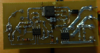
So far I have been collecting the board according to the Chinese version of the scheme, and it looks like it is assembled.
Setting
The circuit requires almost no adjustment, but you need to properly connect the heater and adjust the temperature range. Debugging should be carried out at a reduced volt to 9 supply voltage, otherwise, with a long turn on at 24V, you can heat the sting to red. To determine the correct polarity of the heater connection, I broke the circuit near the variable resistor (did not solder the trimmer resistor) and turned on the regulator. When the soldering iron is turned on with the correct polarity, power is not supplied to it and the LED does not light up. Due to the zero drift of the op-amp, this behavior is possible even if the polarity is incorrect, to check this situation, heat the tip of the sting for half a second with a lighter. If the polarity is not correct, the soldering iron will be powered continuously.
I had a 10k variable resistor available, so the values of the adjustment circuit are somewhat different from the original, after tuning, the adjustment range turned out to be from 260º to 390º. Perhaps I will decide to expand the range further by reducing the resistance of the low-resistance resistor R2.
Tests
In operation, the soldering iron proved to be quite normal. The heating rate turned out to be at a real height of about ten seconds (I cite the video).
With the power of a special miracle, I did not see, unless, of course, compared with cheap Chinese stations, which for the most part do not solder, but pick snot. And so it is quite at the level of simple, but branded stations.

I soldered the adapter with this soldering iron. Although for such a thin sting, this is a perversion. Soldering such massive parts cannot be called comfortable, heat transfer is clearly not enough. The video turned out to be boring and long until I decided not to post it.
In the end, in general, I quite liked the results.
Therefore, I plan to order another more massive sting, until I decided which type to choose BC or D.
And make the station itself into two channels from a computer power supply. There are a lot of articles about it, removing 20-24v and 6a from it doesn’t seem to be a problem either. I tried it on, it seems that after removing unnecessary parts from the PSU board, two regulators will fit into the case. At the same time I'm going to use the block fan as an exhaust hood. Now I use a 12v fan with a piece of a filter from a kitchen hood (in the description it was stated that this felt was like activated carbon), but the thrust of one fan is a bit small and I plan to install two.
By the way, here is the view of today's fan that I use as an exhaust hood.

When I get my hands on it, I'll show you how it turned out. While the soldering iron is simply connected to the laboratory unit. If you feed one soldering iron, then you can use a power supply, for example, from a laptop, I get 19v and 4.5A from a burned-out laptop, which is quite enough for work.
I also give a video demonstrating the speed of heating the soldering iron. Of course, for a more massive tip or at a lower supply voltage, the warm-up time may increase.
The list of elements shows the denominations soldered on the board, the notes indicate the elements on the original circuit.
List of radio elements
| Designation | Type of | Denomination | Quantity | Note | Score | My notepad |
|---|---|---|---|---|---|---|
| U1 | Operational amplifier | LM358A | 1 | To notepad | ||
| U2 | Linear Regulator | LM317M | 1 | LM7806 | To notepad | |
| Q1 | bipolar transistor | 2N2222A | 1 | 9013 | To notepad | |
| Q2 | MOSFET transistor | AO4407A | 1 | IRF9540 | To notepad | |
| D1-D3 | rectifier diode | 1N4148 | 3 | Diode D3 is missing in the original | To notepad | |
| C2 | Capacitor | 10 nF | 1 | To notepad | ||
| C3 | Capacitor | 1 uF | 1 | To notepad | ||
| C4 | Capacitor | 22 uF | 1 | 1 uF | To notepad | |
| C5 | electrolytic capacitor | 470uF | 1 | To notepad | ||
| R1 | Resistor | 22 kOhm | 1 | 30 kOhm | To notepad | |
| R2 | Resistor | 39 ohm | 1 | 51 ohm | To notepad | |
| R3 | Resistor | 100 ohm | 1 | To notepad | ||
| R4 | Resistor | 120 kOhm | 1 | 100 kOhm | To notepad | |
| R5, R6, R13 | Resistor |
Hakko T12 stingers have recently become increasingly popular due to their high quality, ease of use and a large assortment. In total, there are about 80 varieties of stings (more precisely, their tips), which is absolutely enough for any situation. Most users use at most 5-10 varieties in their work, but if necessary, you can always choose exactly the option that is currently required.
Features of Hakko T12 tips for soldering station
Stings of this type are primarily distinguished by a very high heating rate to a working state. On average, using a more or less normal soldering station, it takes about 15 seconds (sometimes less). In addition, such products are equipped with a built-in temperature sensor by default. That is, having a normal soldering iron controller and an external temperature meter, you can set them up so that the temperature varies at a level of 7-10 ° C, no more.
The next important point is ease of use. With most other tips, dismantling is often a problem. You have to spend a lot of time to remove the sting and put a new one. With stings like Hakko T12, this problem does not arise in principle. The entire replacement process takes about five seconds.
Products are shipped in a regular plastic bag. Each of them has three contacts, which are separated from each other by special plastic rings. The length of the sting can vary between 147-154 mm, much depends on the variety. In some cases, they may be slightly longer or shorter. On each of the products there is a sting code and its type (a sticker with these characteristics).
To work with a sting with a diameter of 5.5 millimeters, a voltage of 24 volts and a power of 70 watts is required. They are heated to a temperature of 400 ° C, but can be increased by another +50 degrees. True, this will lead to the fact that the sting will serve much less. And what is important, such stings are freely combined with lead-free solders. All products supplied have tinned tips.
Popular varieties of Hakko T12 stings
It is simply meaningless to list all the varieties of stings from this manufacturer. There are also a lot of options for their use, but there are several types that deservedly enjoy the highest popularity. Let's dwell on them in a little more detail.
So, a T12-K sting vaguely resembles the tip of a clerical knife. Great for heating a large part or multiple contacts. And with it, you can cut synthetics and melt polyethylene.
In different sets of stings Hakko T12 There may be a wide variety of products. Before purchasing, it is recommended to clarify what exactly is included in the package and make the final decision after receiving such information.
Sharp stings T12-D08, T12-B and T12-IL are similar to each other. The tip resembles an awl and the whole difference lies only in what kind of sharpening angle this or that variety will have and the overall diameter of the point. Suitable for almost all standard soldering iron uses. Curved stings T12-JL02 remotely resemble a hook and are used in cases where it is impossible to get close to the part directly. In general, for any hard-to-reach places.
T12-D4 and T12-D24 are devices similar to a chisel in their tip. The scope of application is extremely extensive, but suitable for almost everything. And the last of the common variations: T12-BC2, T12-C4 and T12-C1. These are universal stings, the only difference between which lies in the diameter of the tip. They are the most commonly used, and therefore they also fail more often.
The popular Hakko T12 kit allows you to make a good soldering station for little money. This set has already been considered on the muska, which is why I decided to purchase it. Under the cut, my experience of assembling a station in a case from available components. Perhaps someone will be useful.
What happened in the end. 
The assembly of the handle is described in detail in the previous review, so I will not consider it. I will only note that the main thing is to be careful when positioning the pads. It is important that both pads for soldering the spring-loaded contact are side by side on the same side, because if you make a mistake, then soldering is quite difficult. I have seen this error in several reviewers on youtube. 
Since the Chinese pinout picture looks a little confusing, I decided to draw a more understandable one. The order of contacts from the vibration sensor to the controller does not matter.

In the comments, there was a dispute about the correct position of the vibration sensor, also known as the SW-200D angle sensor. This sensor is used to automatically switch the soldering iron to standby mode, in which the temperature of the tip becomes 200C until the soldering iron is picked up again. The only correct position of the sensor was experimentally established. The transition to sleep mode occurs if no changes come from the sensor for more than 10 minutes and, accordingly, exit from sleep mode occurs if at least some fluctuations were recorded. 
In this sensor, vibration indications are possible only at the moment when the balls touch the contact area. If the balls are in a glass, then no data will be received. Therefore, the sensor must be soldered with the glass up, and the pad towards the sting. The glass at the sensor looks like an all-metal edge, and the contact pad is made of yellowish plastic.
If you place the sensor with the glass down (towards the tip), then the sensor will not work when the soldering iron is placed vertically and it will have to be shaken to exit sleep mode. 
The sleep timeout can be adjusted in the menu. To go to the configuration menu, you need to hold down the button on the encoder (press the temperature controller) with the controller power off, turn on the controller and release the button.
Sleep time is adjusted in P08. You can set a value from 3 minutes to 50, others will be ignored.
To move between menu items, you need to briefly hold down the button of the encoder.
P01 ADC reference voltage (obtained by measuring the TL431)
P02 NTC correction (by setting the temperature to the lowest reading on the digital observation)
P03 op amp input offset voltage correction value
P04 thermocouple amplifier gain
P05 PID parameters pGain
P06 PID parameters iGain
P07 PID parameters dGain
P08 automatic shutdown time setting 3-50 minutes
P09 restore factory settings
P10 temperature settings stepping
P11 thermocouple amplifier gain
If for some reason the vibration sensor interferes with you, you can turn it off by closing SW and + on the controller.
In order to squeeze the maximum power out of the soldering iron, it must be powered by 24V. With a power supply of 19V and above, do not forget to remove the resistor 
Components Used
The soldering iron itself is a replica of the Hakko T12 with a controller

The most useful was T12-BC1 
It turned out that for each sting you need to calibrate the temperature separately. I managed to achieve a discrepancy of a couple of degrees. 
In general, I am very pleased with the soldering iron. Together with a normal flux, I learned how to solder SMD at a level that I had never dreamed of before.
On the Internet you can find a lot of materials about this wonderful soldering iron. But I will also share my experience of assembling a soldering station kit on Hakko T12 tips. And in the next article we will talk about assembling a soldering station with a hairdryer. So the set comes with:

2. The controller itself, a connector for connecting a soldering iron, an LED, a handle for an encoder and two displacement sensors (they are placed in the handle and bring the soldering iron out of sleep mode when the soldering iron is removed from the stand, one is generally needed, but was sent with a margin).

3. Cable (in elastic insulation).

4. Handle for installing the sting.

5. Wires and heat shrinks (these wires are needed if you plan to install a soldering iron connector not on the board, but take it out).

6. Solder and rosin (to assemble the kit, the seller carefully put some solder and a box of rosin).

Handle Assembly
Let's start by assembling a soldering handle on Hakko T12 tips. She assembles simply. We install a round textolite washer in the groove and solder it. Soldering pads are provided on one side only. For greater reliability, on the other hand, I cleaned the mask and soldered it there too.


Displacement sensor
Next, you need to solder the displacement sensor. There are some explanations for it. This sensor is an ordinary tube into which two leads enter and there is a metal ball inside. In one of the positions, the ball closes these two outputs, and in the other it opens. Connect it to the multimeter in continuity mode and turn first with one lead down then the other. Mark the output when the downward direction of which the sensor is triggered. Now, if the soldering iron is in your stand with the tip down, then this pin needs to be soldered to 2, if the tip is up, then this pin is soldered to 1.

Wiring

From the side of the board we see -, -, SW, +, E. You need to solder like this:
Fee Pen
— —
- A
SW B
+ +
E earth
From the side of the handle, the cable is fixed to the ties.
DO NOT FORGET TO PUT THE HANDLE AND THE CONNECTOR COVER ON THE CABLE BEFORE UNSOLDERING!!!


The final assembly of the handle consists in installing the sting and fixing elements. 


Board Assembly
Now for the board assembly. Actually, here you just need to solder the LED and the socket for the soldering iron. But! Its fastening nut is located on the side of the terminals, and if it is soldered now, then later, when installed in the case, you will have to solder it. The installation sequence in the case, if the socket is not on the wires, is as follows: we mark the holes in the case, screw the socket, then install the board (the connector pins enter the mating holes of the board), screw the encoder, and solder the connector. In this case, the calibration resistor will remain covered by the panel. To avoid this, you can make a hole in the panel opposite it, or you can solder it back, which I did (but in this case you will have to recalibrate the station later).