Homemade soldering station based on Hakko T12. Soldering station on STC for tips like Hakko T12 Hakko t12 different type of thermocouple
What is a sting Hakko T12? This is a cartridge that includes a soldering iron tip, heater and thermocouple. Now gaining popularity and the network is full of articles about them. Due to the fact that they were repeated by the Chinese, the prices for them on Ali are around $ 4, and you can often buy a stock for a piece at a price of around $ 3. The range of these stings is wide, it is claimed that there are more than 80 models. (By the way, T15 are the same stings that are fully compatible with T12)
I was attracted to these stings too after watching the reviews. One of the highlights is fast heating. When you are debugging or repairing, you often need to solder one wire or replace some part, and waiting every time the soldering iron heats up is annoying, and keeping it on all the time, in addition to reducing the resource, does not make the air in the room cleaner. Here, heating is literally in ten seconds, i.e. while he dripped the flux and took the tweezers, the soldering iron is ready. Also not a bad opportunity to warm up large landfills.
Putting it all together the right way with a store-bought quick-change soldering iron handle, etc. for the money it’s not too justified, since a ready-made station like BK950D costs $ 35-40 on AliExpress.
Therefore, I decided to simplify everything as much as possible by refusing to change the stings. In principle, as a rule, only a pair of stings is used in work, rarely three. I decided to just make a couple of soldering irons to get a two-channel soldering station.
So I bought one T12-KU tip for testing.
The tip rod at the end has two contact belts, between them a heater with a resistance of 8 ohms and a thermocouple are connected in series. Supply voltage up to 24V and current up to 3A. The maximum power is about 70W.
If you look from the far side of the heater, then first it goes plus then minus and the body of the cartridge itself is the ground and serves to ground the sting.

I fixed the wires to these belts with a simple twist and crimped them with several heat shrinks.

Two thickenings are visible on the sting rod. After the second thickening from the tip of the sting, the rod has a low temperature, and here you can already take it with your hands. In this place I wound paper with ordinary stationery glue.

If there is a ready-made soldering iron handle or a suitable tube, then you can already glue the rod. But since I didn’t have anything at hand, I also glued the pen out of office paper.
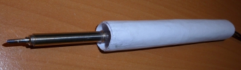
Of course, after each layer of paper, the glue must be allowed to dry. After complete drying, I crimped the heat shrink on top to make it less dirty and more pleasant to hold.

At the back, to increase rigidity, I filled it with glue (there is literally not a large ring of glue).

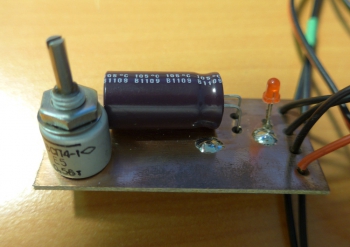
The temperature controller made analog based on a circuit from Chinese regulators. The polarity of the heater is not indicated on the diagram, plus the heater according to the diagram from above, the minus is connected to the ground of the circuit.

Just redone for existing parts. I replaced the 7806 stabilizer with LM317, Q1 2N2222, Q2 AO4407 and added a protective diode D3. I bring a drawing of a printed circuit board, it is made on a two-sided textolite, the second side is under an earthen polygon. All smd resistors and ceramic capacitors size 0805. Additional shunt capacitors 0.1uF, but you can not install. C4 size B.

The only scarce part in this circuit is the P-Mosfet.
I also tried converting the circuit for N-Mosfet, which are much easier to get or dig out.

WARNING. The circuit does not work when using LM358. I managed to run it using the TL082 op-amp, he gave his own version in the comments.
Zener diode D3 and transistor Q2 took the first ones that came across. Any zener diode for current> 20mA and voltage 6v. A transistor for a voltage of more than 40V and a current of more than 6A (with a power supply of less than 20V, you can install Mosfet from old motherboards, they are usually for a voltage of 30V).
Resistor R15 and voltage source V1, this is the heater and thermocouple of the soldering iron.
So far I have been collecting the board according to the Chinese version of the scheme, and it looks like it is assembled.

Setting
The circuit requires almost no adjustment, but you need to properly connect the heater and adjust the temperature range. Debugging should be carried out at a reduced volt to 9 supply voltage, otherwise, with a long turn on at 24V, you can heat the sting to red. To determine the correct polarity of the heater connection, I broke the circuit near the variable resistor (did not solder the trimmer resistor) and turned on the regulator. When the soldering iron is turned on with the correct polarity, power is not supplied to it and the LED does not light up. Due to the zero drift of the op-amp, this behavior is possible even if the polarity is incorrect, to check this situation, heat the tip of the sting for half a second with a lighter. If the polarity is not correct, the soldering iron will be powered continuously.
I had a 10k variable resistor available, so the values of the adjustment circuit are somewhat different from the original, after tuning, the adjustment range turned out to be from 260º to 390º. Perhaps I will decide to expand the range further by reducing the resistance of the low-resistance resistor R2.
Tests
In operation, the soldering iron proved to be quite normal. The heating rate turned out to be at a real height of about ten seconds (I cite the video).
With the power of a special miracle, I did not see, unless, of course, compared with cheap Chinese stations, which for the most part do not solder, but pick snot. And so it is quite at the level of simple, but branded stations.

I soldered the adapter with this soldering iron. Although for such a thin sting, this is a perversion. Soldering such massive parts cannot be called comfortable, heat transfer is clearly not enough. The video turned out to be boring and long until I decided not to post it.
In the end, in general, I quite liked the results.
Therefore, I plan to order another more massive sting, until I decided which type to choose BC or D.
And make the station itself into two channels from a computer power supply. There are a lot of articles about it, removing 20-24v and 6a from it doesn’t seem to be a problem either. I tried it on, it seems that after removing unnecessary parts from the PSU board, two regulators will fit into the case. At the same time I'm going to use the block fan as an exhaust hood. Now I use a 12v fan with a piece of a filter from a kitchen hood (in the description it was stated that this felt was like activated carbon), but the thrust of one fan is a bit small and I plan to install two.
By the way, here is the view of today's fan that I use as an exhaust hood.

When I get my hands on it, I'll show you how it turned out. While the soldering iron is simply connected to the laboratory unit. If you feed one soldering iron, then you can use a power supply, for example, from a laptop, I get 19v and 4.5A from a burned-out laptop, which is quite enough for work.
I also give a video demonstrating the speed of heating the soldering iron. Of course, for a more massive tip or at a lower supply voltage, the warm-up time may increase.
The list of elements shows the denominations soldered on the board, the notes indicate the elements on the original circuit.
List of radio elements
| Designation | Type of | Denomination | Quantity | Note | Score | My notepad |
|---|---|---|---|---|---|---|
| U1 | Operational amplifier | LM358A | 1 | To notepad | ||
| U2 | Linear Regulator | LM317M | 1 | LM7806 | To notepad | |
| Q1 | bipolar transistor | 2N2222A | 1 | 9013 | To notepad | |
| Q2 | MOSFET transistor | AO4407A | 1 | IRF9540 | To notepad | |
| D1-D3 | rectifier diode | 1N4148 | 3 | Diode D3 is missing in the original | To notepad | |
| C2 | Capacitor | 10 nF | 1 | To notepad | ||
| C3 | Capacitor | 1 uF | 1 | To notepad | ||
| C4 | Capacitor | 22 uF | 1 | 1 uF | To notepad | |
| C5 | electrolytic capacitor | 470uF | 1 | To notepad | ||
| R1 | Resistor | 22 kOhm | 1 | 30 kOhm | To notepad | |
| R2 | Resistor | 39 ohm | 1 | 51 ohm | To notepad | |
| R3 | Resistor | 100 ohm | 1 | To notepad | ||
| R4 | Resistor | 120 kOhm | 1 | 100 kOhm | To notepad | |
| R5, R6, R13 | Resistor |
The popular Hakko T12 kit allows you to make a good soldering station for little money. This set has already been considered on the muska, which is why I decided to purchase it. Under the cut, my experience of assembling a station in a case from available components. Perhaps someone will be useful.
What happened in the end. 
The assembly of the handle is described in detail in the previous review, so I will not consider it. I will only note that the main thing is to be careful when positioning the pads. It is important that both pads for soldering the spring-loaded contact are side by side on the same side, because if you make a mistake, then soldering is quite difficult. I have seen this error in several reviewers on youtube. 
Since the Chinese pinout picture looks a little confusing, I decided to draw a more understandable one. The order of contacts from the vibration sensor to the controller does not matter.

In the comments, there was a dispute about the correct position of the vibration sensor, also known as the SW-200D angle sensor. This sensor is used to automatically switch the soldering iron to standby mode, in which the temperature of the tip becomes 200C until the soldering iron is picked up again. The only correct position of the sensor was experimentally established. The transition to sleep mode occurs if no changes come from the sensor for more than 10 minutes and, accordingly, exit from sleep mode occurs if at least some fluctuations were recorded. 
In this sensor, vibration indications are possible only at the moment when the balls touch the contact area. If the balls are in a glass, then no data will be received. Therefore, the sensor must be soldered with the glass up, and the pad towards the sting. The glass at the sensor looks like an all-metal edge, and the contact pad is made of yellowish plastic.
If you place the sensor with the glass down (towards the tip), then the sensor will not work when the soldering iron is placed vertically and it will have to be shaken to exit sleep mode. 
The sleep timeout can be adjusted in the menu. To go to the configuration menu, you need to hold down the button on the encoder (press the temperature controller) with the controller power off, turn on the controller and release the button.
Sleep time is adjusted in P08. You can set a value from 3 minutes to 50, others will be ignored.
To move between menu items, you need to briefly hold down the button of the encoder.
P01 ADC reference voltage (obtained by measuring the TL431)
P02 NTC correction (by setting the temperature to the lowest reading on the digital observation)
P03 op amp input offset voltage correction value
P04 thermocouple amplifier gain
P05 PID parameters pGain
P06 PID parameters iGain
P07 PID parameters dGain
P08 automatic shutdown time setting 3-50 minutes
P09 restore factory settings
P10 temperature settings stepping
P11 thermocouple amplifier gain
If for some reason the vibration sensor interferes with you, you can turn it off by closing SW and + on the controller.
In order to squeeze the maximum power out of the soldering iron, it must be powered by 24V. With a power supply of 19V and above, do not forget to remove the resistor 
Components Used
The soldering iron itself is a replica of the Hakko T12 with a controller

The most useful was T12-BC1 
It turned out that for each sting you need to calibrate the temperature separately. I managed to achieve a discrepancy of a couple of degrees. 
In general, I am very pleased with the soldering iron. Together with a normal flux, I learned how to solder SMD at a level that I had never dreamed of before.
Reading local reviews, I have repeatedly thought about buying a soldering iron with a T12 tip. For a long time I wanted something portable on the one hand, powerful enough on the other hand, and, of course, maintaining the temperature normally.
I have a relatively large number of soldering irons, bought at different times and for different tasks:
There are very ancient EPSN-40 and a 90W Moskabel, a slightly newer EMP-100 (hatchet), a completely new Chinese TLW 500W. The last two keep the temperature especially well (even when soldering copper pipes), but soldering microcircuits with them is not very convenient :). An attempt to use the ZD-80 (pistol with a button) did not work out - neither power nor normal temperature maintenance. Other "electronic" trifles such as Antex cs18 / xs25 are suitable only for very small things, and they have no built-in adjustment. About 15 years ago I used den-on "ovskim ss-8200, but the stings there are very tiny, the temperature sensor is far away and the temperature gradient is huge - despite the declared 80W, there won't be even a third on the sting.
As a stationary option, I have been using Lukey 868 for 10 years (it's practically 702, only a ceramic heater and some other little things). But there is no portability in it, you can’t take it with you in your pocket or small bag.
Because at the time of purchase, I was not yet sure “do I need it”, the minimum budget option was taken with a K-sting and a handle that was as similar as possible to the usual soldering iron from Lukey. It is possible that for some it does not seem very convenient, but for me it is more important that the handles of both soldering irons used are habitually and equally in the hand.
The further review can be conditionally divided into two parts - “how to make a device out of spare parts” and an attempt to analyze “how this device and controller firmware work”.
Unfortunately, the seller removed this particular SKU, so I can only give a link to a snapshot of the product from the order log. However, there is no problem to find a similar product.
Part 1 - construction
After a mock test of performance, the question arose about the choice of design.There was an almost suitable power supply (24v 65W), almost 1: 1 high with a control board, a little narrower than it and about 100mm long. Considering that this power supply fed some kind of dead (not his fault!) connected and not cheap lucent piece of iron, and its output rectifier has two diode assemblies for a total of 40A, I decided that it is not much worse than the one common here Chinese on 6A. At the same time, it will not roll.
Test check on a time-tested load dummy (PEV-100, unscrewed by about 8 ohms)

showed that the PSU practically does not heat up - in 5 minutes of operation, the key transistor, despite its insulated case, heated up to 40 degrees (slightly warm), the diodes are warmer (but it doesn’t burn the hand, it’s quite comfortable to hold), and the voltage is still 24 volts with pennies. Emissions increased to hundreds of millivolts, but for this voltage and this application, this is quite normal. Actually, I stopped the experiment because of the load resistor - about 50W stood out on its smaller half and the temperature exceeded a hundred.
As a result, the minimum dimensions were determined (PSU + control board), the next step was the case.
Since one of the requirements was portability, up to the ability to shove it into your pockets, the option with ready-made cases disappeared. The available universal plastic cases were not at all suitable in size, the Chinese aluminum cases under T12 for jacket pockets are also too big, and I didn’t want to wait another month. The option with a "printed" case did not pass - neither strength nor heat resistance. Having estimated the possibilities and recalling the pioneer youth, I decided to make it from the ancient one-sided foil fiberglass, lying around since the times of the USSR. Thick foil (a micrometer on a carefully smoothed piece showed 0.2mm!) still did not allow etching tracks thinner than a millimeter due to lateral etching, but for the body - that's it.
But laziness, coupled with an unwillingness to dust, categorically did not approve of sawing with a hacksaw or cutter. After assessing the available technological capabilities, I decided to try the option of sawing textolite on an electric tile cutter. As it turned out - a highly convenient option. The disk cuts fiberglass without any effort, the edge is almost perfect (you can’t even compare with a cutter, hacksaw or jigsaw), the width along the length of the cut is also the same. And, importantly, all the dust remains in the water. It is clear that if you need to saw off one small piece, then unfolding the tile cutter is too long. But even for this small body, it was necessary to cut a meter.
Next, a case with two compartments was soldered - one for the power supply, the second for the control board. Initially, I didn't plan the separation. But, as in welding, plates soldered into the corner tend to reduce the angle when they cool, and an additional membrane is very useful.
The front panel is bent from aluminum in the shape of the letter P. The upper and lower bends are threaded for fixing in the case.
The result is this (I am still “playing” with the device, so the painting is still very rough, from the remains of an old spray can and without polishing):

The overall dimensions of the body itself are 73 (width) x 120 (length) x 29 (height). The width and height cannot be made smaller, because the control board measures 69 x 25, and finding a shorter power supply is also not easy.
At the back there is a connector for a standard electrical wire and a switch:

Unfortunately, the black microswitch was not in the trash, it will be necessary to order it. On the other hand, white is more noticeable. But I specifically set the connector as standard - this allows in most cases not to take an additional wire with me. Unlike the option with a laptop outlet.
Bottom view:

The black rubber insulator was left over from the original power supply. It is quite thick (a little less than a millimeter), heat-resistant and very difficult to cut (hence the rough cutout for the plastic spacer - it almost didn’t fit). Feels like asbestos impregnated with rubber.
To the left of the power supply is the rectifier radiator, to the right is the key transistor. In the original PSU, the radiator was a thin strip of aluminum. I decided to "aggravate" just in case. Both heatsinks are isolated from the electronics, so they can freely adhere to the copper surfaces of the case.
An additional heatsink for the control board is mounted on the membrane, contact with d-pak cases is provided by a thermal pad. There are not many benefits, but everything is better than air. To eliminate the short circuit, I had to bite off the protruding contacts of the "aviation" connector a little.
For clarity, a soldering iron next to the case:

Result:
1) The soldering iron works approximately as stated and fits perfectly in the pockets of the jacket.
2) Recycled in the old trash and no longer lying around: a power supply, a piece of fiberglass 40 years old, a can of nitro enamel made in 1987, a microswitch and a small piece of aluminum.
Of course, from the point of view of economic feasibility, it is much easier to buy a ready-made case. Although the materials were practically free, but “time is money”. It’s just that the task “make it cheaper” did not appear on my list of tasks at all.
Part 2 - Operation Notes
As you can see, in the first part, I did not mention at all how it all works. It seemed to me appropriate not to confuse the description of my personal design (rather "collective-farm self-made" in my opinion) and the functioning of the controller, which is identical or similar to many.As a preliminary warning, I would like to say:
1) Different controllers have slightly different circuitry. Even externally identical boards can have slightly different components. Because I only have one particular device of mine, I can't guarantee a match with others in any way.
2) The controller firmware that I analyzed is not the only one available. It is common, but you may have a different firmware that functions in a different way.
3) I do not at all claim to be a pioneer. Many points have already been previously covered by other reviewers.
4) Then there will be a lot of boring letters and not a single funny picture. If you are not interested in the internal device - stop here.
Design overview
Further calculations will be largely related to the controller circuitry. To understand its operation, the exact scheme is not necessary, it is enough to consider the main components:1) STC15F204EA microcontroller. Nothing particularly outstanding chip of the 8051 family, noticeably faster than the original (original 35 years ago, yes). It is powered by 5V, has a 10-bit ADC with a switch, 2x512 bytes nvram, 4K program memory.
2) Stabilizer for + 5V, consisting of 7805 and a powerful resistor to reduce heat dissipation (?) by 7805, with a resistance of 120-330 ohms (different on different boards). The solution is extremely low-cost and heat-generating.
3) Power transistor STD10PF06 with strapping. Works in key mode at low frequency. Nothing outstanding, old man.
4) Thermocouple voltage amplifier. The trimmer adjusts its gain. It has protection at the input (from 24V) and is connected to one of the inputs of the ADC MK.
5) Reference voltage source on TL431. Connected to one of the inputs of the ADC MK.
6) Board temperature sensor. Also connected to the ADC.
7) Indicator. Connected to MK, works in dynamic indication mode. I suspect that one of the main consumers + 5V
8) Control knob. Rotation regulates the temperature (and other parameters). The button line in many models is not soldered or cut. If connected, it allows you to configure additional parameters.
As you can see, all functioning is determined by the microcontroller. Why the Chinese put just this one - I don’t know, it’s not very cheap (about $ 1, if you take a few pieces) and back to back in terms of resources. In a typical Chinese firmware, literally a dozen bytes of program memory remain free. The firmware itself is written in C or something similar (obvious tails of the library are visible there).
Functioning of the controller firmware
I don't have the source code, but IDA hasn't gone away :). The mechanism of operation is quite simple.At initial startup, the firmware:
1) initializes the device
2) loads parameters from nvram
3) Checks if the button is pressed, if it is pressed, it waits for release and starts the p / p settings of advanced parameters (Pxx) There are many parameters, if there is no understanding, then it is better not to touch them. I can lay out the layout, but I'm afraid to provoke problems.
4) Displays "SEA", waits and starts the main work loop
There are several modes of operation:
1) Normal, normal temperature maintenance
2) Partial energy saving, temperature 200 degrees
3) Complete shutdown
4) Setting mode P10(temperature setting step) and P4(thermocouple op amp gain)
5) Alternate control mode
After starting, mode 1 works.
A short press of the button switches to mode 5. There you can turn the knob to the left and go to mode 2 or to the right - increase the temperature by 10 degrees.
A long press switches to mode 4.
In previous reviews, there was a lot of debate about how to properly install the vibration sensor. According to the firmware I have, I can say unequivocally - no difference. The transition to the partial power saving mode is performed in the absence of changes
the state of the vibration sensor, the absence of significant changes in the temperature of the tip and the absence of signals from the handle - all this for 3 minutes. The vibration sensor is closed or open - it does not matter at all, the firmware analyzes only changes in the state. The second part of the criterion is also interesting - if you are soldering, then the tip temperature will inevitably float. And if a deviation of more than 5 degrees from the set value is fixed, there will be no exit to the energy saving mode.
If the power saving mode lasts longer than the specified one, the soldering iron will turn off completely, the indicator will show zeros.
Exit from energy-saving modes - by vibration or by the control knob. There is no return from full energy saving to partial.
The MK is engaged in maintaining the temperature in one of the timer interrupts (two of them are involved, the second is engaged in the display and other things. Why this is done is not clear - the interrupt interval and other settings are the same, it was quite possible to do with a single interrupt). The control cycle consists of 200 timer interrupts. At the 200th interruption, the heating is necessarily turned off (- as much as 0.5% of the power!), A delay is performed, after which the voltages are measured from the thermocouple, temperature sensor and reference voltage from TL431. Further, all this is converted into temperature using formulas and coefficients (partially specified in nvram).
Here I will allow myself a small digression. Why a temperature sensor in such a configuration is not entirely clear. When properly organized, it should give a temperature correction at the cold junction of the thermocouple. But in this design, it measures the temperature of the board, which has nothing to do with the required one. You either need to transfer it to the pen, as close as possible to the T12 cartridge (and another question is where the cold junction of the thermocouple is located in the cartridge), or throw it away altogether. Perhaps I don’t understand something, but it seems that the Chinese developers stupidly torn the compensation scheme from some other device, completely not understanding the principles of operation.
After measuring the temperature, the difference between the set temperature and the current temperature is calculated. Depending on whether it is large or small, two formulas work - one large, with a bunch of coefficients and accumulation of deltas (those who wish can read about the construction of PID controllers), the second is simpler - with large differences, you need to either heat it as much as possible or turn it off completely (depending on from the sign). The PWM variable can have a value from 0 (disabled) to 200 (fully enabled) - according to the number of interrupts in the control loop.
When I just turned on the device (and had not yet got into the firmware), I was interested in one moment - there was no jitter by ± degrees. Those. The temperature either keeps stable, or twitches immediately by 5-10 degrees. After analyzing the firmware, it turned out that it was apparently always trembling. But if the deviation from the set temperature is less than 2 degrees, the firmware shows not the measured, but the set temperature. This is neither good nor bad - the trembling low bit is also very annoying - just something to keep in mind.
Concluding the conversation about the firmware, I want to note a few more points.
1) I have not worked with thermocouples for 20 years already. Maybe during this time they have become linear;), but earlier, for any accurate measurements and if possible, the non-linearity correction function was always introduced - by a formula or a table. Here it is not from the word at all. Only zero offset and slope can be adjusted. Maybe all cartridges use high-linear thermocouples. Either the individual spread in different cartridges is greater than the possible group non-linearity. I would like to hope for the first option, but experience hints at the second ...
2) For some reason I don't understand, inside the firmware the temperature is set as a fixed point number with a resolution of 0.1 degrees. It is quite obvious that due to the previous remark, 10-bit ADC, incorrect cold end correction, unshielded wire, etc. the real accuracy of measurements and 1 degree will not be in any way. Those. It looks like it was ripped off again from some other device. And the complexity of calculations has slightly increased (repeatedly you have to divide / multiply by ten 16-bit numbers).
3) There are contact pads Rx/TX/gnd/+5v on the board. As I understand it, the Chinese had special firmware and a special Chinese program that allows you to directly receive data from all three ADC channels and adjust the PID parameters. But there is nothing of this in the standard firmware, the outputs are intended solely for uploading the firmware to the controller. The fill program is available, works through a simple serial port, only TTL levels are needed.
4) The points on the indicator have their own functionality - the left one indicates mode 5, the middle one - the presence of vibration, the right one - the type of displayed temperature (set or current).
5) 512 bytes are allotted for recording the selected temperature. The entry itself was done correctly - each change is written to the next free cell. As soon as the end is reached, the block is completely erased, and the entry is made in the first cell. When enabled, the furthest recorded value is taken. This allows you to increase the resource by a couple of hundred times.
Owner, remember - by turning the temperature knob, you are wasting an irreplaceable resource of the built-in nvram!
6) For other settings, the second nvram block is used
Everything is with the firmware, if you have any additional questions - ask.
Power
One of the important characteristics of a soldering iron is the maximum power of the heater. You can evaluate it as follows:1) We have a voltage of 24V
2) We have a T12 sting. The cold tip resistance I measured is just over 8 ohms. I got 8.4, but I do not presume to claim that the measurement error is less than 0.1 Ohm. Let's assume that the real resistance is no less than 8.3 Ohm.
3) The resistance of the STD10PF06 key in the open state (according to the datasheet) - no more than 0.2 Ohm, typical - 0.18
4) Additionally, you need to take into account the resistance of 3 meters of wire (2x1.5) and connector.
The resulting cold circuit resistance is at least 8.7 ohms, which gives a current limit of 2.76A. Taking into account the drop on the key, wires and connector, the voltage on the heater itself will be about 23V, which will give a power of about 64 watts. Moreover, this is the maximum power in a cold state and without taking into account the duty cycle. But do not get too upset - 64 watts is quite a lot. And given the design of the sting, it is enough for most cases. Checking the performance in the constant heating mode, I placed the tip of the sting in a mug of water - the water around the sting boiled and soared very cheerfully.
But here's an attempt to save money using a power supply from a laptop has a very dubious efficiency - an outwardly insignificant decrease in voltage leads to a loss of a third of the power: instead of 64 W, about 40 W will remain. Is this $6 savings worth it?
If, on the contrary, you try to squeeze the declared 70W out of the soldering iron, there are two ways:
1) Slightly increase the voltage of the PSU. It is enough to increase by only 1V.
2) Reduce the circuit resistance.
Almost the only option to slightly reduce the resistance of the circuit is to replace the key transistor. Unfortunately, almost all p-channel transistors in the package used and for the required voltage (I would not risk setting it to 30V - the margin will be minimal) have similar Rdson. And so it would be doubly wonderful - at the same time, the controller board would be heated less. Now, in the maximum heating mode, about a watt is released on the key transistor.
Temperature accuracy/stability
In addition to power, temperature stability is equally important. Moreover, for me personally, stability is even more important than accuracy, because if the value on the indicator can be selected empirically - I usually do this (and it’s not very important that at an exhibition of 300 degrees it’s really on the sting - 290), then instability cannot be overcome in this way . However, according to the sensations, the temperature stability on the T12 is noticeably better than on the stings of the 900 series.What makes sense to redo in the controller
1) The controller is getting hot. Not fatal, but more than desired. Moreover, it is mainly not even the power unit that heats it, but the 5V stabilizer. Measurements showed that the current at 5V is about 30 mA. 19V drop at 30mA gives approximately 0.6W of continuous heating. Of these, about 0.1W is allocated on the resistor (120Ω) and another 0.5W on the stabilizer itself. The consumption of the rest of the circuit can be ignored - only 0.15W, of which a significant part is spent on the indicator. But the board is small and there is simply nowhere to put a step-down - if only on a separate scarf.2) A power switch with a large (relatively large!) resistance. The use of a 0.05 ohm switch would remove all heating problems and add about a watt of power to the cartridge heater. But the case would no longer be 2 mm dpak, but at least a size larger. Or even change the control to the n-channel.
3) Transferring ntc to the handle. But then it makes sense to transfer the microcontroller, the power switch and the reference voltage there.
4) Extension of firmware functionality (several sets of PID parameters for different tips, etc.). Theoretically possible, but personally it’s easier (and cheaper!) for me to re-blind on some younger stm32 than to trample into existing memory.
As a result, we have a wonderful situation - you can redo a lot of things, but almost any alteration requires you to throw out the old board and make a new one. Or don't touch it, which is what I'm leaning towards for now.
Conclusion
Does it make sense to switch to T12? Don't know. For now, I'm only working with the T12-K tip. For me, it is one of the most versatile - and the polygon heats up well, and you can solder / desolder the comb of leads with an ersatz wave, and you can warm up a separate lead with a sharp end.On the other hand, the existing controller and the lack of automatic identification of a particular type of tip complicates the work with the T12. Well, what prevented Hakko from putting some sort of identifying resistor/diode/chip inside the cartridge? It would be ideal if the controller had several slots for individual tip settings (at least 4 pieces) and when changing the tip, it automatically loaded the necessary ones. And in the existing system, you can make a manual selection of the sting as much as possible. Estimating the amount of work, you understand that the game is not worth the candle. Yes, and the cost of cartridges is commensurate with the whole soldering station (if you do not take China for $5). Yes, of course, you can experimentally display a table of temperature corrections and stick a plate on the lid. But with the PID coefficients (on which stability directly depends), this cannot be done. From sting to sting, they must be different.
If we discard thoughts-dreams, then the following comes out:
1) If there is no soldering station, but you want to, it's better to forget about 900 and take T12.
2) If you need cheap and accurate soldering modes are not much needed - it's better to take a simple soldering iron with power control.
3) If you already have a soldering station for 900x, then T12-K is enough - versatility and portability turned out to be on top.
Personally, I am satisfied with the purchase, but I do not plan to replace all the existing 900th stings with T12 yet.
This is my first review, so I apologize in advance for possible roughness.
Hakko T12 stingers have recently become increasingly popular due to their high quality, ease of use and a large assortment. In total, there are about 80 varieties of stings (more precisely, their tips), which is absolutely enough for any situation. Most users use at most 5-10 varieties in their work, but if necessary, you can always choose exactly the option that is currently required.
Features of Hakko T12 tips for soldering station
Stings of this type are primarily distinguished by a very high heating rate to a working state. On average, using a more or less normal soldering station, it takes about 15 seconds (sometimes less). In addition, such products are equipped with a built-in temperature sensor by default. That is, having a normal soldering iron controller and an external temperature meter, you can set them up so that the temperature varies at a level of 7-10 ° C, no more.
The next important point is ease of use. With most other tips, dismantling is often a problem. You have to spend a lot of time to remove the sting and put a new one. With stings like Hakko T12, this problem does not arise in principle. The entire replacement process takes about five seconds.
Products are shipped in a regular plastic bag. Each of them has three contacts, which are separated from each other by special plastic rings. The length of the sting can vary between 147-154 mm, much depends on the variety. In some cases, they may be slightly longer or shorter. On each of the products there is a sting code and its type (a sticker with these characteristics).
To work with a sting with a diameter of 5.5 millimeters, a voltage of 24 volts and a power of 70 watts is required. They are heated to a temperature of 400 ° C, but can be increased by another +50 degrees. True, this will lead to the fact that the sting will serve much less. And what is important, such stings are freely combined with lead-free solders. All products supplied have tinned tips.
Popular varieties of Hakko T12 stings
It is simply meaningless to list all the varieties of stings from this manufacturer. There are also a lot of options for their use, but there are several types that deservedly enjoy the highest popularity. Let's dwell on them in a little more detail.
So, a T12-K sting vaguely resembles the tip of a clerical knife. Great for heating a large part or multiple contacts. And with it, you can cut synthetics and melt polyethylene.
In different sets of stings Hakko T12 There may be a wide variety of products. Before purchasing, it is recommended to clarify what exactly is included in the package and make the final decision after receiving such information.
Sharp stings T12-D08, T12-B and T12-IL are similar to each other. The tip resembles an awl and the whole difference lies only in what kind of sharpening angle this or that variety will have and the overall diameter of the point. Suitable for almost all standard soldering iron uses. Curved stings T12-JL02 remotely resemble a hook and are used in cases where it is impossible to get close to the part directly. In general, for any hard-to-reach places.
T12-D4 and T12-D24 are devices similar to a chisel in their tip. The scope of application is extremely extensive, but suitable for almost everything. And the last of the common variations: T12-BC2, T12-C4 and T12-C1. These are universal stings, the only difference between which lies in the diameter of the tip. They are the most commonly used, and therefore they also fail more often.
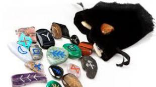
For my birthday I was presented with a soldering station with replaceable tips HAKKO T12. There were three stings in the kit, of which I use 2, and then for poverty. Now we managed to take a set of stings for review - 10 pieces.
What is good about this type of sting? Firstly, they heat up quickly - they heat up to the operating temperature in 12-15 seconds.
Secondly, a built-in temperature sensor. It is possible, in the presence of a normal soldering iron controller and an external temperature meter, to rebuild within + -7-10 degrees.
Thirdly - quick-detachable. Replacing one sting with another takes 5 seconds.
Fourth, the range

Of course, the Chinese brothers make copies, generally of good quality.
What is such a set for? Due to the wide range of parts, it is necessary to keep a wide range of stings. There is a universal type - but of different sizes, there is for soldering massive parts, needle-shaped - for small smd parts, a poker - where it is inconvenient to crawl to the part ...
As a result, if you are engaged in soldering different types of parts, 5-7 pieces of stings are formed, which you often use.
But back to the set.

It arrived in this form, it was packed in a cardboard box and a little bubble wrap.

The tips have 3 contacts separated by plastic rings.
The length of the sting in the set ranges from 147 to 154 mm - depending on the type.
Each sting has a sticker with the sting type and code.
Blade diameter 5.5 mm
Supply voltage - 24 volts
Power 70 watts
Temperature - up to 400 degrees (it is possible up to 450 - but the service time is reduced)
Compatible with lead-free solders
The set contains the following tips:
T12-B
T12-BC2
T12-D4
T12-C1
T12-C4
T12-D08
T12-D24
T12-IL
T12-JL02
T12-K


T12-K - it is convenient to heat several contacts or a massive part, from non-standard - to weld polyethylene or cut synthetic fabric.


T12-D08, similar in shape T12-B and T12-IL differ in diameter and sharpening angle

T12-JL02 - used in hard to reach places

T12-D4, T12-D24 - Chisel sharpening


T12-BC2,T12-C1,T12-C4 "hoof" - diameter 1, 2 and 4 mm universal tip sharpening
All stingers came with a tinned tip.
They solder well, when soldering with ordinary rosin with a temperature of over 300, black soot forms on the tip, it is better to use specialized fluxes.
Personally, in the kit I don’t have enough “microwave” sting and with a recess for soldering output elements.
After a month of use, I did not find any traces of burning out of the sting. Copper would have had to be sharpened twice already.
Nice set for a decent price.
The product was provided for writing a review by the store. The review is published in accordance with clause 18 of the Site Rules.
I plan to buy +24 Add to favorites Liked the review +13 +31