Methods for selecting compressor-condenser units for supply systems. Installation of main devices and auxiliary equipment
Evaporators
In the evaporator, the liquid refrigerant boils and turns into a vapor state, removing heat from the cooled medium.
Evaporators are divided into:
by type of cooled medium - for cooling gaseous media (air or other gas mixtures), for cooling liquid heat carriers (coolants), for cooling solids (products, technological substances), evaporators-condensers (in cascade refrigeration machines Oh);
depending on the conditions of movement of the cooled media - with natural circulation of the cooled medium, with forced circulation of the cooled medium, for cooling stationary media (contact cooling or freezing of products);
according to the method of filling - flooded and non-flooded types;
according to the method of organizing the movement of the refrigerant in the apparatus - with natural circulation of the refrigerant (circulation of the refrigerant under the action of a pressure difference); with forced coolant circulation (with circulation pump);
depending on the method of organizing the circulation of the cooled liquid - with a closed system of the cooled liquid (shell-and-tube, shell-and-coil), with an open system of the cooled liquid (panel).
Most often, the medium for cooling is air - a universal coolant that is always available. Evaporators differ in the type of channels in which the refrigerant flows and boils, the profile of the heat exchange surface and the organization of air movement.
Types of evaporators
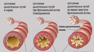
Sheet-tube evaporators are used in household refrigerators. Made from two sheets with stamped channels. After the channels are aligned, the sheets are joined by roller welding. The assembled evaporator can be given the appearance of a U- or O-shaped structure (in the form of a low-temperature chamber). The heat transfer coefficient of sheet-tube evaporators is from 4 to 8 V / (m-square * K) at a temperature difference of 10 K.
a, b - O-shaped; c - panel (shelf-evaporator)
Smooth-tube evaporators are coils of pipes that are attached to the racks with brackets or soldering. For ease of installation, smooth-tube evaporators are made in the form of wall-mounted batteries. A battery of this type (wall-mounted smooth-tube evaporative batteries of the BN and BNI types) is used on ships to equip storage chambers food products. To cool the provisional chambers, smooth-tube wall-mounted batteries designed by VNIIkholodmash (ON26-03) are used.

Finned-tube evaporators are most widely used in commercial refrigeration equipment. Evaporators are made of copper pipes with a diameter of 12, 16, 18 and 20 mm with a wall thickness of 1 mm or brass tape L62-T-0.4 with a thickness of 0.4 mm. To protect the surface of pipes from contact corrosion, they are coated with a layer of zinc or chrome plated.
To equip refrigerating machines with a capacity of 3.5 to 10.5 kW, IRSN evaporators are used (dry wall-mounted finned-tube evaporator). Evaporators are made from copper pipe with a diameter of 18 x 1 mm, finning - from a brass tape 0.4 mm thick with a rib pitch of 12.5 mm.
A finned-tube evaporator equipped with a fan for forced air circulation is called an air cooler. The heat transfer coefficient of such a heat exchanger is higher than that of a finned evaporator, and therefore the dimensions and weight of the apparatus are smaller.
evaporator malfunction technical heat transfer

Shell and tube evaporators are evaporators with closed circulation of the cooled liquid (heat transfer medium or liquid process medium). The liquid to be cooled flows through the evaporator under pressure generated by the circulation pump.
In shell-and-tube flooded evaporators, the refrigerant boils on the outer surface of the tubes, and the liquid to be cooled flows inside the tubes. The closed circulation system allows to reduce the refrigeration system due to the reduction of contact with air.
To cool water, shell-and-tube evaporators are often used with the refrigerant boiling inside the tubes. The heat exchange surface is made in the form of pipes with internal fins and the refrigerant boils inside the pipes, and the cooled liquid flows in the annulus.
Operation of evaporators

· During the operation of evaporators, it is necessary to comply with the requirements of the manufacturer's instructions, these Rules and production instructions.
· When the pressure on the discharge lines of the evaporators is higher than that provided for by the project, the electric motors and heat carriers of the evaporators should automatically turn off.
· It is not allowed to operate evaporators with faulty or switched off ventilation, with faulty instrumentation or their absence, if there is a gas concentration in the room that exceeds 20% of the lower concentration limit of flame propagation.
· Information about the mode of operation, the amount of time worked by compressors, pumps and evaporators, as well as malfunctions in operation, should be reflected in the operating log.
· Conclusion of evaporators from the operating mode to the reserve must be carried out in accordance with the production instructions.
· After switching off the evaporator, the shut-off valves on the suction and discharge lines must be closed.
· The air temperature in the evaporator compartments during working hours should not be lower than 10 °C. When the air temperature is below 10 °C, it is necessary to drain the water from the water supply, as well as from the cooling system of the compressors and the heating system of the evaporators.
· In the evaporator compartments must be technological schemes equipment, piping and instrumentation, plant operating instructions and operating logs.
· Maintenance evaporators is carried out by operating personnel under the guidance of a specialist.
· Maintenance evaporative equipment includes maintenance and inspection operations, partial disassembly of equipment with repair and replacement of wearing parts and parts.
During the operation of evaporators, the requirements for safe operation pressure vessels.
· Maintenance and repair of evaporators must be carried out in the scope and terms specified in the manufacturer's passport. Maintenance and repair of gas pipelines, fittings, automatic safety devices and instrumentation of evaporators must be carried out within the time limits established for this equipment.
Operation of evaporators is not allowed in the following cases:
1) increasing or decreasing the pressure of the liquid and vapor phases above or below the established norms ;
2) malfunctions of safety valves, instrumentation and automation equipment;
3) failure to verify instrumentation;
4) failure of fasteners;
5) detection of gas leakage or sweating in welds, bolted joints, as well as violations of the integrity of the evaporator structure;
6) ingress of the liquid phase into the gas pipeline of the vapor phase;
7) stopping the supply of coolant to the evaporator.
Evaporator repair
Too weak evaporator . Generalization of symptoms
In this section, we will define the "evaporator too weak" fault as any fault that leads to an abnormal reduction in cooling capacity due to the fault of the evaporator itself.

Diagnosis algorithm

The "evaporator too weak" fault, and the resulting abnormal evaporation pressure drop, is the most easily detected as this is the only fault in which a normal or slightly reduced superheat occurs simultaneously with an abnormal evaporation pressure drop.
Practical aspects
Dirty pipes and heat exchange fins of the evaporator
The danger of this defect occurs mainly in plants that are poorly maintained. A typical example of such an installation is an air conditioner that does not have an air filter at the evaporator inlet.
When cleaning the evaporator, it is sometimes enough to blow the fins with a jet of compressed air or nitrogen in the direction opposite to the air movement during operation of the unit, but to completely cope with the dirt, it is often necessary to use special cleaning and detergents. In some particularly severe cases, it may even be necessary to replace the evaporator.
Dirty air filter
In air conditioners, fouling of the air filters installed at the evaporator inlet leads to an increase in airflow resistance and, as a result, a drop in air flow through the evaporator, which causes an increase in temperature difference. Then the repairman must clean or change the air filters (for filters of similar quality), not forgetting to ensure free access to outside air when installing new filters.
It seems useful to recall that the air filters must be in perfect condition. Especially at the outlet facing the evaporator. The filter media must not be allowed to be torn or lose thickness during repeated washes.
If the air filter is in poor condition or not suitable for the evaporator, dust particles will not be captured well and will cause fouling of the evaporator tubes and fins over time.
Evaporator fan belt slipping or broken
If the fan belt(s) slip, the fan speed drops resulting in a reduction in evaporator airflow and an increase in air temperature drop (at the limit if the belt is broken, there is no airflow at all).
Before tightening the belt, the repairman should check for wear and replace if necessary. Of course, the repairer should also check the alignment of the belts and thoroughly inspect the drive (cleanliness, mechanical clearances, grease, tension), as well as the condition of the drive motor with the same care as the fan itself. Each repairman, of course, cannot have all existing models of drive belts in stock in his car, so you first need to check with the client and select the right kit.
Poorly adjusted pulley with variable chute width
Most modern air conditioners are equipped with fan drive motors, on the axis of which a pulley of variable diameter (variable chute width) is installed.
At the end of the adjustment, it is necessary to fix the movable cheek on the threaded part of the hub using a locking screw, while the screw should be tightened as tightly as possible, carefully making sure that the screw leg rests against a special flat on the threaded part of the hub and prevents damage to the thread. Otherwise, if the thread is crushed by the locking screw, further adjustment of the depth of the gutter will be difficult, and may even be impossible. After adjusting the pulley, in any case, check the current consumed by the electric motor (see description of the following fault).
High pressure loss in the evaporator air path
If a the variable diameter pulley is adjusted to the maximum fan speed and the air flow is still insufficient, which means that the losses in the air path are too high in relation to the maximum fan speed.
After you have firmly convinced that there are no other problems (a damper or valve is closed, for example), it should be considered advisable to replace the pulley in such a way as to increase the fan speed. Unfortunately, increasing the speed of the fan requires not only the replacement of the pulley, but also entails other consequences.
The evaporator fan rotates in the opposite direction
The risk of such a malfunction always exists when commissioning a new installation, when the evaporator fan is equipped with a three-phase drive motor (in this case, it is sufficient to swap two phases to restore the desired direction of rotation).
The fan motor, being powered by a 60 Hz mains supply, is connected to a 50 Hz mains supply
This problem, fortunately quite rare, can mainly affect motors made in the USA and intended to be plugged into the network. alternating current with a frequency of 60 Hz. Note that some motors made in Europe and intended for export may also require a 60 Hz supply frequency. You can quickly understand the cause of this malfunction very simply enough for the repairman to read specifications motor on a special plate attached to it.
Pollution of a large number of evaporator fins
If many evaporator fins are covered with dirt, the resistance to air movement through it increased, which leads to a decrease in air flow through the evaporator and an increase in air temperature drop.
And then the repairman will have no choice but to thoroughly clean the contaminated parts of the evaporator fins on both sides with a special comb with a tooth pitch that exactly matches the distance between the fins.
Evaporator Maintenance
It consists in providing heat removal from the heat transfer surface. For this purpose, the supply of liquid refrigerant to the evaporators and air coolers is regulated to create the required level in flooded systems or in the amount necessary to ensure optimal superheating of the exhaust steam in non-flooded ones.
The safety of operation of evaporative systems largely depends on the regulation of the refrigerant supply and the order in which the evaporators are turned on and off. The refrigerant supply is regulated in such a way as to prevent vapor breakthrough from the side high pressure. This is achieved by smooth control operations, maintaining the required level in the linear receiver. When connecting disconnected evaporators to a running system, it is necessary to prevent the wet running of the compressor, which can occur due to the release of steam from the heated evaporator along with drops of liquid refrigerant during its sudden boiling after careless or ill-conceived opening of the shut-off valves.
The connection order of the evaporator, regardless of the duration of the shutdown, must always be as follows. Stop the supply of refrigerant to the running evaporator. Close the suction valve on the compressor and gradually open the shut-off valve on the evaporator. After that, the compressor suction valve is also gradually opened. Then regulate the flow of refrigerant to the evaporators.
To ensure an efficient heat transfer process in the evaporators of refrigeration units with brine systems, ensure that the entire heat transfer surface is immersed in the brine. In open type evaporators, the brine level should be 100-150 mm above the evaporator section. During the operation of shell-and-tube evaporators, the timely release of air through the air valves is monitored.
When servicing evaporative systems, they monitor the timeliness of thawing (thawing) of the frost layer on batteries and air coolers, check whether the melt water drainage pipeline is frozen, monitor the operation of fans, the density of closing hatches and doors to avoid loss of cooled air.
During defrosting, the uniformity of the supply of heating vapors is monitored, preventing uneven heating of individual parts of the apparatus and not exceeding the heating rate of 30 CCH.
The supply of liquid refrigerant to air coolers in pumpless installations is controlled by the level in the air cooler.
In installations with a pump circuit, the uniformity of the refrigerant flow to all air coolers is regulated depending on the freezing rate.
Bibliography
Installation, operation and repair refrigeration equipment. Textbook (Ignatiev V.G., Samoilov A.I.)
→ Installation of refrigeration units
Installation of main devices and auxiliary equipment
The main devices of a refrigeration plant include devices that are directly involved in mass and heat transfer processes: condensers, evaporators, subcoolers, air coolers, etc. Receivers, oil separators, dirt traps, air separators, pumps, fans and other equipment included in the refrigeration plant include to ancillary equipment.
The installation technology is determined by the degree of factory readiness and design features of the devices, their weight and installation design. First, the main devices are installed, which allows you to start laying pipelines. To prevent moistening of thermal insulation, a layer of waterproofing is applied to the supporting surface of apparatus operating at low temperatures, a thermal insulation layer is laid, and then a waterproofing layer is laid again. To create conditions that exclude the formation of thermal bridges, all metal parts (fastening belts) are placed on the apparatus through wooden antiseptic bars or spacers 100-250 mm thick.
Heat exchangers. Most of the heat exchangers are supplied by the factories ready for installation. So, shell-and-tube condensers, evaporators, subcoolers are supplied assembled, elemental, spray, evaporative condensers and panel, immersion evaporators - assembly units. Finned tube evaporators, direct expansion coils and brine evaporators can be fabricated on site from sections of finned tubes by the installer.
Shell-and-tube devices (as well as capacitive equipment) are mounted in a flow-combined way. When laying welded machines on supports, make sure that all welds are available for inspection, tapping with a hammer during survey, and also for repair.
The horizontality and verticality of the devices are checked by level and plumb or with the help of geodetic instruments. Permissible deviations of the devices from the vertical are 0.2 mm, horizontally - 0.5 mm per 1 m. If the device has a collector or sump, a slope is only allowed in their direction. The verticality of the shell-and-tube vertical condensers is especially carefully verified, since it is necessary to ensure the film runoff of water along the walls of the pipes.
Elemental capacitors (due to the high metal content they are used in rare cases in industrial installations) are installed on metal frame, above the receiver by elements from the bottom up, checking the horizontality of the elements, the one-planeness of the flanges of the fittings and the verticality of each section.
The installation of spray and evaporative condensers consists of a sequential installation of a sump, heat exchange pipes or coils, fans, oil separator, pump and fittings.
Air-cooled units used as condensers in refrigeration units are mounted on a pedestal. To center the axial fan relative to the guide vane, slots in the plate are used, which allow the gearbox plate to be moved in two directions. The fan motor is centered on the gearbox.
Panel brine evaporators are placed on an insulating layer, on a concrete pad. The metal tank of the evaporator is mounted on wooden bars, mount the agitator and brine valves, connect the drain pipe and test the tank for density by pouring water. The water level should not fall during the day. Then the water is drained, the bars are removed and the tank is lowered onto the base. Panel sections are tested with air at a pressure of 1.2 MPa before installation. Then the sections are mounted in the tank in turn, collectors, fittings, liquid separator are installed, the tank is filled with water and the evaporator assembly is again tested with air at a pressure of 1.2 MPa.

Rice. 1. Installation of horizontal condensers and receivers using the in-line method:
a, b - in a building under construction; c - on supports; g - on flyovers; I - the position of the capacitor in front of the slinging; II, III - positions when moving the crane boom; IV - installation on supporting structures

Rice. 2. Installation of capacitors:
0 - elemental: 1 - supporting metal structures; 2 - receiver; 3 - capacitor element; 4 - plumb line for checking the verticality of the section; 5 - level to check if the element is horizontal; 6 - ruler for checking the location of the flanges in the same plane; b - irrigation: 1 - water drain; 2 - pallet; 3 - receiver; 4 - sections of coils; 5 - supporting metal structures; 6 - water distribution trays; 7 - water supply; 8 - overflow funnel; c - evaporative: 1 - water collector; 2 - receiver; 3, 4 - level indicator; 5 - nozzles; 6 - drop eliminator; 7 - oil separator; eight - safety valves; 9 - fans; 10 - precondenser; 11 - float water level regulator; 12 - overflow funnel; 13 - pump; g - air: 1 - supporting metal structures; 2 - drive frame; 3 - guide apparatus; 4 - section of ribbed heat exchange tubes; 5 - flanges for connecting sections to collectors
Immersion evaporators are mounted in a similar way and tested with an inert gas pressure of 1.0 MPa for systems with R12 and 1.6 MPa for systems with R22.

Rice. 2. Mounting the panel brine evaporator:
a - testing the tank with water; b - testing of panel sections with air; c - installation of panel sections; d - test of the evaporator with water and air as an assembly; 1 - wooden bars; 2 - tank; 3 - mixer; 4 - panel section; 5 - goats; 6 - air supply ramp for testing; 7 - water drain; 8 - oil collector; 9-liquid separator; 10 - thermal insulation
Capacitive equipment and auxiliary devices. Linear ammonia receivers are mounted on the high pressure side below the condenser (sometimes under it) on the same foundation, and the steam zones of the apparatuses are connected by an equalizing line, which creates conditions for draining liquid from the condenser by gravity. During installation, the difference in height marks from the liquid level in the condenser (the level of the outlet pipe from the vertical condenser) to the level of the liquid pipe from the overflow cup of the oil separator AND is not less than 1500 mm (Fig. 25). Depending on the brands of the oil separator and the linear receiver, the differences in the height marks of the condenser, receiver and oil separator Yar, Yar, Nm and Ni, specified in the reference literature, are maintained.
On the low pressure side, drainage receivers are installed for draining ammonia from cooling devices when a snow coat is thawed by hot ammonia vapors and protective receivers in pumpless circuits for receiving liquid in case it is ejected from the batteries with an increase in heat load, as well as circulating receivers. Horizontal circulation receivers are mounted together with liquid separators placed above them. In vertical circulating receivers, the vapor is separated from the liquid in the receiver.

Rice. 3. Scheme of installation of the condenser, linear receiver, oil separator and air cooler in the ammonia refrigeration unit: KD - condenser; LR - linear receiver; HERE - air separator; SP - overflow glass; MO - oil separator
In refrigerant aggregated installations, linear receivers are installed above the condenser (without an equalizing line), and refrigerant enters the receiver in a pulsating flow as the condenser is filled.
All receivers are equipped with safety valves, pressure gauges, level indicators and shutoff valves.
Intermediate vessels are installed on supporting structures on wooden beams, taking into account the thickness of the thermal insulation.
cooling batteries. Direct-cooled freon batteries are supplied by manufacturers ready for installation. Brine and ammonia batteries are manufactured at the installation site. Brine batteries are made from steel electric-welded pipes. For the manufacture of ammonia batteries, seamless hot-rolled steel pipes (usually 38X3 mm in diameter) are used from steel 20 for operation at temperatures up to -40 ° C and from steel 10G2 for operation at temperatures up to -70 ° C.
Cold-rolled low-carbon steel strip is used for transverse-spiral finning of battery tubes. Pipes are finned on a semi-automatic equipment in the conditions of procurement workshops with a selective check with a probe of the density of fit of the fins to the pipe and a given fin spacing (usually 20 or 30 mm). Finished pipe sections are hot-dip galvanized. In the manufacture of batteries, semi-automatic welding in a carbon dioxide environment or manual arc welding is used. Finned tubes are connected and the batteries are connected by collectors or coils. Collector, rack and coil batteries are assembled from unified sections.
After testing ammonia batteries with air for 5 minutes for strength (1.6 MPa) and for 15 minutes for density (1 MPa), the welded joints are subjected to galvanizing with an electroplating gun.
Brine batteries are tested with water after installation at a pressure equal to 1.25 working pressure.
Batteries are attached to embedded parts or metal structures on ceilings (ceiling batteries) or on walls (wall batteries). Ceiling batteries are mounted at a distance of 200-300 mm from the axis of the pipes to the ceiling, wall batteries - at a distance of 130-150 mm from the axis of the pipes to the wall and at least 250 mm from the floor to the bottom of the pipe. When mounting ammonia batteries, the following tolerances are maintained: in height ± 10 mm, deviation from the verticality of wall-mounted batteries - no more than 1 mm per 1 m of height. When installing batteries, a slope of not more than 0.002 is allowed, and in the direction opposite to the movement of the refrigerant vapor. Wall-mounted batteries are mounted with cranes before the installation of floor slabs or with the help of loaders with an arrow. Ceiling batteries are mounted using winches through blocks attached to the ceilings.
Air coolers. They are installed on a pedestal (stand-mounted air coolers) or attached to embedded parts on ceilings (mounted air coolers).
Post-mounted air coolers are mounted by the flow-combined method using a jib crane. Before installation, insulation is laid on the pedestal and a hole is made for connecting a drainage pipeline, which is laid with a slope of at least 0.01 towards the drain in sewer network. Mounted air coolers are mounted in the same way as ceiling batteries.

Rice. 4. Battery mounting:
a - batteries with an electric forklift; b - ceiling battery with winches; 1 - overlap; 2- embedded parts; 3 - block; 4 - slings; 5 - battery; 6 - winch; 7 - electric forklift
Cooling batteries and air coolers made of glass pipes. For the manufacture of coil-type brine batteries, glass pipes are used. Pipes are attached to racks only in straight sections (rolls are not fixed). The supporting metal structures of the batteries are attached to the walls or suspended from the ceilings. The distance between the posts should not exceed 2500 mm. Wall-mounted batteries to a height of 1.5 m are protected by mesh fences. The glass pipes of air coolers are mounted in a similar way.
For the manufacture of batteries and air coolers, pipes with smooth ends are taken, connecting them with flanges. After the installation is completed, the batteries are tested with water at a pressure equal to 1.25 working pressure.
Pumps. Centrifugal pumps are used to pump ammonia and other liquid refrigerants, coolants and chilled water, condensate, as well as to free drainage wells and circulate cooling water. To supply liquid refrigerants, only hermetically sealed glandless pumps of the XG type with an electric motor built into the pump housing are used. The stator of the electric motor is sealed, and the rotor is mounted on one shaft with impellers. The shaft bearings are cooled and lubricated by liquid refrigerant withdrawn from the discharge pipe and then transferred to the suction side. Sealed pumps are installed below the liquid intake point at a liquid temperature below -20 ° C (in order to prevent the pump from stalling, the suction pressure is 3.5 m).

Rice. 5. Installation and alignment of pumps and fans:
a - installation centrifugal pump along the logs with a winch; b - installation of a fan with a winch using braces
Before installing stuffing box pumps, check their completeness and, if necessary, carry out an audit.
Centrifugal pumps are installed on the foundation with a crane, a hoist, or along logs on rollers or a sheet of metal using a winch or levers. When installing the pump on a foundation with blind bolts embedded in its array, wooden beams are placed near the bolts so as not to jam the thread (Fig. 5, a). Check elevation, levelness, centering, presence of oil in the system, smoothness of rotation of the rotor and stuffing of the stuffing box (stuffing box). Stuffing box
The gland must be carefully stuffed and evenly bent without distortion. Excessive tightening of the stuffing box leads to its overheating and an increase in power consumption. When installing the pump above the receiving tank, a check valve is installed on the suction pipe.
Fans. Most fans are supplied as a unit ready for installation. After the fan is installed by a crane or a winch with guy wires (Fig. 5, b) on the foundation, pedestal or metal structures (through vibration isolating elements), the height and horizontality of the installation are verified (Fig. 5, c). Then they remove the device locking the rotor, inspect the rotor and housing, make sure that there are no dents or other damage, manually check the smooth rotation of the rotor and the reliability of fastening all parts. Check the gap between the outer surface of the rotor and the housing (not more than 0.01 of the wheel diameter). Measure the radial and axial runout of the rotor. Depending on the size of the fan (its number), the maximum radial runout is 1.5-3 mm, axial runout is 2-5 mm. If the measurement shows an excess of tolerance, static balancing is carried out. The gaps between the rotating and fixed parts of the fan are also measured, which should be within 1 mm (Fig. 5, d).
During a trial run, within 10 minutes, the level of noise and vibration is checked, and after stopping, the reliability of fastening of all connections, the heating of the bearings and the condition of the oil system. The duration of the test under load is 4 hours, while checking the stability of the fan under operating conditions.
Installation of cooling towers. Small film-type cooling towers (I PV) are delivered for installation with a high degree of prefabrication. The horizontal position of the cooling tower installation is verified, connected to the pipeline system, and after filling the water cycle system with softened water, the uniformity of irrigation of the nozzle from miplast or polyvinyl chloride plates is regulated by changing the position of the water spray nozzles.
When installing larger cooling towers after the construction of the pool and building structures install a fan, align its alignment with the cooling tower diffuser, adjust the position of the water distribution gutters or collectors and nozzles to evenly distribute water over the irrigation surface.

Rice. 6. Alignment of the impeller of the axial fan of the cooling tower with the guide vane:
a - by moving the frame relative to the supporting metal structures; b - cable tension: 1 - impeller hub; 2 - blades; 3 - guide apparatus; 4 - casing of the cooling tower; 5 - supporting metal structures; 6 - gearbox; 7 - electric motor; 8 - centering cables
Alignment is regulated by moving the frame and the electric motor in the grooves for the mounting bolts (Fig. 6, a), and in the largest fans, the alignment is achieved by adjusting the tension of the cables attached to the guide vane and supporting metal structures (Fig. 6, b). Then check the direction of rotation of the electric motor, smooth running, runout and vibration level at the operating speeds of rotation of the shaft.
In order to increase the safety of operation of the refrigeration plant, condensers, in-line receivers and oil separators (high-pressure apparatus) with large quantity coolant should be placed outside the engine room.
This equipment, as well as refrigerant storage receivers, must be surrounded by a metal barrier with a lockable entrance. Receivers must be protected by a canopy from sunlight and precipitation. Apparatus and vessels installed indoors can be located in the compressor shop or in a special control room if it has a separate exit to the outside. The passage between a smooth wall and the device must be at least 0.8 m, but it is allowed to install devices near walls without passages. The distance between the protruding parts of the apparatus must be at least 1.0 m, and if this passage is the main one - 1.5 m.
When mounting vessels and apparatuses on brackets or cantilever beams, the latter must be embedded in the main wall to a depth of at least 250 mm.
It is allowed to install devices on columns using clamps. It is forbidden to punch holes in columns for fixing equipment.
For installation of devices and further maintenance of condensers and circulation receivers, metal platforms with a fence and a ladder are arranged. With a platform length of more than 6 m, there should be two stairs.
Platforms and stairs must have handrails and rims. The height of the handrails is 1 m, the edges are not less than 0.15 m. The distance between the posts of the handrails is not more than 2 m.
Tests of devices, vessels and pipeline systems for strength and density are carried out upon completion installation work and within the time limits stipulated by the Rules for the Design and Safe Operation of Ammonia Refrigeration Units.
Horizontal cylindrical devices. Shell-and-tube evaporators, horizontal shell-and-tube condensers and horizontal receivers are installed on concrete foundations in the form of separate pedestals strictly horizontally with an allowable slope of 0.5 mm per 1 m of linear length towards the oil sump.
The devices rest on wooden antiseptic bars with a width of at least 200 mm with a recess in the shape of the body (Fig. 10 and 11) and are attached to the foundation with steel belts with rubber gaskets.

Low-temperature apparatuses are installed on bars with a thickness not less than the thickness of thermal insulation, and under
belts place wooden bars with a length of 50-100 mm and a height equal to the thickness of the insulation, at a distance of 250-300 mm from each other around the circumference (Fig. 11).
To clean the pipes of condensers and evaporators from contamination, the distance between their end caps and walls should be 0.8 m on one side and 1.5-2.0 m on the other. When installing the devices in a room to replace the tubes of condensers and evaporators, a “false window” is arranged (in the wall opposite the cover of the device). To do this, an opening is left in the masonry of the building, which is filled with heat-insulating material, sewn up with boards and plastered. When repairing devices, the “false window” is opened, and after the repair is completed, it is restored. Upon completion of work on the placement of devices, automation and control devices, shut-off valves, and safety valves are mounted on them.
The cavity of the apparatus for the refrigerant is purged compressed air, the strength and density test is carried out with the covers removed. When mounting a capacitor-receiver unit, a horizontal shell-and-tube condenser is installed on the site above the linear receiver. The size of the site should provide a circular service of the apparatus.
Vertical shell-and-tube condensers. The devices are installed outdoors on a massive foundation with a pit for draining water. In the manufacture of the foundation, the bolts for fastening the lower flange of the apparatus are laid in concrete. The condenser is installed by a crane on packs of linings and wedges. By tamping wedges, the apparatus is set strictly vertically with the help of plumb lines located in two mutually perpendicular planes. In order to prevent the swinging of plumb lines by the wind, their weights are lowered into a container with water or oil. The vertical arrangement of the apparatus is caused by the helical flow of water through its tubes. Even with a slight tilt of the apparatus, water will not normally wash the surface of the pipes. At the end of the alignment of the apparatus, the linings and wedges are welded into packages and the foundation is poured.
Evaporative condensers. Supplied for installation as an assembly and installed on a site, the dimensions of which allow for circular maintenance of these devices. ‘The height of the site is taken into account the placement of linear receivers under it. For ease of maintenance, the platform is equipped with a ladder, and if the fans are located on the top, it is additionally installed between the platform and the upper plane of the apparatus.
After installing the evaporative condenser, connect to it circulation pump and pipelines.

The most widespread are evaporative condensers of the TVKA and Evako types manufactured by VNR. The baffle layer of these devices is made of plastic, so welding and other work with an open flame should be prohibited in the area where the devices are installed. Fan motors are grounded. When installing the device on a hill (for example, on the roof of a building), it is necessary to use lightning protection.
Panel evaporators. Supplied as separate units, and their assembly is carried out during installation work.
The evaporator tank is tested for tightness by pouring water and installed on a concrete slab 300-400 mm thick (Fig. 12), the height of the underground part of which is 100-150 mm. Between the foundation and the tank, wooden antiseptic beams or railway sleepers and thermal insulation are laid. Panel sections are installed in the tank strictly horizontally, according to the level. Side surfaces the tank is insulated and plastered, the mixer is adjusted.
Chamber devices. Wall and ceiling batteries are assembled from unified sections (Fig. 13) at the installation site.

For ammonia batteries, sections of pipes with a diameter of 38X2.5 mm are used, for a coolant - with a diameter of 38X3 mm. The pipes are finned with spirally wound ribs made of 1X45 mm steel tape with a rib spacing of 20 and 30 mm. The characteristics of the sections are presented in table. 6.

The total length of battery hoses in pump circuits should not exceed 100-200 m. The battery is installed in the chamber using embedded parts fixed in the ceiling during the construction of the building (Fig. 14).

Battery hoses are placed strictly horizontally in level.
Ceiling coolers are supplied for assembled installation. The supporting structures of the devices (channels) are connected to the channels of embedded parts. The horizontality of the installation of the apparatus is checked by the hydrostatic level.
Batteries and air coolers are lifted to the place of installation of the devices by loaders or other lifting devices. The permissible slope of the hoses must not exceed 0.5 mm per 1 m linear length.
To remove melt water during defrosting, drain pipes are installed on which heating elements of the ENGL-180 type are fixed. The heating element is a glass fiber tape based on high resistivity metal heating wires. The heating elements are spirally wound onto the pipeline or laid linearly, fixed on the pipeline with glass tape (for example, LES-0.2X20 tape). On the vertical section of the drain pipeline, heaters are installed only in a spiral. During linear laying, the heaters are fixed to the pipeline with glass tape with a step of not more than 0.5 m. After fixing the heaters, the pipeline is insulated with non-combustible insulation and sheathed with a protective metal sheath. In places of significant bends of the heater (for example, on flanges), an aluminum tape 0.2-1.0 mm thick and 40-80 mm wide should be placed under it to avoid local overheating.
At the end of the installation, all devices are tested for strength and density.
One of the most important elements for vapor compression machine is . It performs the main process of the refrigeration cycle - selection from the cooled medium. Other elements of the refrigeration circuit, such as a condenser, expansion device, compressor, etc., only ensure the reliable operation of the evaporator, so it is the choice of the latter that must be given due attention.
It follows from this that, when selecting equipment for a refrigeration unit, it is necessary to start with the evaporator. Many novice repairmen often admit typical mistake and start the assembly of the installation with the compressor.
On fig. 1 shows a diagram of the most common vapor compression refrigeration machine. Its cycle, given in coordinates: pressure R and i. On fig. 1b points 1-7 of the refrigeration cycle, is an indicator of the state of the refrigerant (pressure, temperature, specific volume) and coincides with that in Fig. 1a (state parameter functions).
Rice. 1 - Scheme and in the coordinates of a conventional vapor compression machine: RU expansion device, Рk- condensation pressure, Ro- boiling pressure.
Graphic image fig. 1b displays the state and functions of the refrigerant, which vary with pressure and enthalpy. Line segment AB on the curve in Fig. 1b characterizes the refrigerant in the state of saturated vapor. Its temperature corresponds to the initial boiling point. The proportion of refrigerant vapor in is 100% and the superheat is close to zero. To the right of the curve AB the refrigerant has a state (the temperature of the refrigerant is greater than the boiling point).
Dot AT is critical for this refrigerant, since it corresponds to the temperature at which the substance cannot go into a liquid state, no matter how high the pressure is. On segment BC, the refrigerant has a state of saturated liquid, and on the left side it has a state of supercooled liquid (the temperature of the refrigerant is less than the boiling point).
Inside the curve ABC the refrigerant is in the state of a vapor-liquid mixture (the proportion of vapor per unit volume is variable). The process occurring in the evaporator (Fig. 1b) corresponds to the segment 6-1 . The refrigerant enters the evaporator (point 6) in the state of a boiling vapor-liquid mixture. In this case, the proportion of steam depends on a specific refrigeration cycle and is 10-30%.
At the outlet of the evaporator, the boiling process may not be completed and the point 1 may not match the dot 7 . If the temperature of the refrigerant at the outlet of the evaporator is higher than the boiling point, then we get an evaporator with overheating. Its magnitude ΔToverheat is the difference between the temperature of the refrigerant at the outlet of the evaporator (point 1) and its temperature on the saturation line AB (point 7):
ΔToverheat=T1 - T7
If points 1 and 7 coincide, then the temperature of the refrigerant is equal to the boiling point, and the superheat ΔToverheat will be equal to zero. Thus, we get a flooded evaporator. Therefore, when choosing an evaporator, a choice must first be made between a flooded evaporator and an evaporator with superheat.
Note that, under equal conditions, a flooded evaporator is more advantageous in terms of the intensity of the heat removal process than with overheating. But it should be taken into account that at the outlet of the flooded evaporator, the refrigerant is in a state of saturated vapor, and it is impossible to supply a humid environment to the compressor. Otherwise, there is a high probability of water hammer, which will be accompanied by mechanical destruction of the compressor parts. It turns out that if you choose a flooded evaporator, then it is necessary to provide additional protection for the compressor from the ingress of saturated steam into it.
If a superheated evaporator is preferred, then there is no need to worry about protecting the compressor and getting saturated steam into it. The probability of occurrence of hydraulic shocks will occur only in the event of a deviation from the required indicator of the magnitude of overheating. AT normal conditions operation of the refrigeration unit superheat value ΔToverheat should be in the range of 4-7 K.
When the overheating indicator decreases ΔToverheat, the intensity of the selection of heat from the environment increases. But at extremely low values ΔToverheat(less than 3K), there is a possibility of wet steam entering the compressor, which can cause water hammer and, consequently, damage to the mechanical components of the compressor.
Otherwise, with a high reading ΔToverheat(more than 10 K), this indicates that insufficient refrigerant is entering the evaporator. The intensity of heat removal from the cooled medium sharply decreases and the thermal regime of the compressor deteriorates.
When choosing an evaporator, another question arises related to the boiling point of the refrigerant in the evaporator. To solve it, it is first necessary to determine what temperature of the cooled medium should be provided for the normal operation of the refrigeration unit. If air is used as the cooled medium, then in addition to the temperature at the outlet of the evaporator, it is also necessary to take into account the humidity at the outlet of the evaporator. Now consider the temperature behavior of the cooled medium around the evaporator during the operation of a conventional refrigeration unit (Fig. 1a).
In order not to delve into this topic, we will neglect the pressure losses on the evaporator. We will also assume that the ongoing heat exchange between the refrigerant and the environment is carried out according to the once-through scheme.
In practice, such a scheme is not often used, since it is inferior to the counterflow scheme in terms of heat transfer efficiency. But if one of the coolants has a constant temperature, and the overheating readings are small, then the forward and counterflow will be equivalent. It is known that the average value of the temperature difference does not depend on the flow pattern. Consideration of the once-through scheme will provide us with a more visual representation of the heat exchange that occurs between the refrigerant and the cooled medium.
First, let's introduce a virtual value L, equal to the length of the heat exchange device (condenser or evaporator). Its value can be determined from the following expression: L=W/S, where W– corresponds to the internal volume of the heat exchange device in which the refrigerant circulates, m3; S is the heat exchange surface area m2.
If we are talking about a refrigeration machine, then the equivalent length of the evaporator is practically equal to the length of the tube in which the process takes place 6-1 . Therefore, its outer surface is washed by the cooled medium.
First, let's pay attention to the evaporator, which acts as an air cooler. In it, the process of taking heat from the air occurs as a result of natural convection or with the help of forced blowing of the evaporator. It should be noted that the first method is practically not used in modern refrigeration units, since air cooling by natural convection is ineffective.
Thus, we will assume that the air cooler is equipped with a fan that provides forced air blowing of the evaporator and is a tubular-finned heat exchanger (Fig. 2). Its schematic representation is shown in Fig. 2b. Let us consider the main quantities that characterize the blowing process.
Temperature difference
The temperature difference across the evaporator is calculated as follows:ΔT=Ta1-Ta2,
where ΔTa is in the range from 2 to 8 K (for tubular-finned evaporators with forced airflow).
In other words, during normal operation of the refrigeration unit, the air passing through the evaporator should be cooled no lower than 2 K and no higher than 8 K.

Rice. 2 - Scheme and temperature parameters of air cooling on the air cooler:
Ta1 and Ta2– air temperature at the inlet and outlet of the air cooler;
- FF– temperature of the refrigerant;
- L is the equivalent length of the evaporator;
- That is the boiling point of the refrigerant in the evaporator.
Maximum temperature difference
The maximum air temperature difference at the evaporator inlet is determined as follows:DTmax=Ta1 - That
This indicator is used when selecting air coolers, since foreign manufacturers of refrigeration equipment provide values for the cooling capacity of evaporators Qsp depending on the size DTmax. Consider the method of selecting the air cooler of the refrigeration unit and determine the calculated values DTmax. To do this, we give as an example the generally accepted recommendations for selecting the value DTmax:
- for freezers DTmax is in the range of 4-6 K;
- for storage rooms for unpackaged products - 7-9 K;
- for storage chambers for hermetically packed products - 10-14 K;
- for air conditioning units - 18-22 K.
Degree of steam superheat at the outlet of the evaporator
To determine the degree of superheating of the steam at the outlet of the evaporator, use the following form:F=ΔТoverload/DTmax=(Т1-Т0)/(Та1-Т0),
where T1 is the temperature of the refrigerant vapor at the outlet of the evaporator.
This indicator is practically not used in our country, but foreign catalogs provide that the readings of the cooling capacity of air coolers Qsp corresponds to the value F=0.65.
During operation, the value F it is customary to take from 0 to 1. Suppose that F=0, then ΔToverload=0, and the refrigerant leaving the evaporator will be in a saturated vapor state. For this model of air cooler, the actual cooling capacity will be 10-15% more than the figure given in the catalog.
If a F>0.65, then the cooling capacity index for this air cooler model must be less than the value given in the catalog. Let's assume that F>0.8, then the actual performance for this model will be 25-30% more value given in the catalog.
If a F->1, then the cooling capacity of the evaporator Qtest->0(Fig. 3).

Fig.3 - dependence of the cooling capacity of the evaporator Qsp from overheating F
The process depicted in Fig. 2b is also characterized by other parameters:
- arithmetic mean temperature difference DTср=Таср-Т0;
- the average temperature of the air that passes through the evaporator Tasr=(Ta1+Ta2)/2;
- minimum temperature difference DTmin=Ta2-To.

Rice. 4 - Scheme and temperature parameters showing the process of cooling water on the evaporator:
where Te1 and Te2 water temperature at the inlet and outlet of the evaporator;
- FF is the temperature of the refrigerant;
- L is the equivalent length of the evaporator;
- That is the boiling point of the refrigerant in the evaporator.
If the temperature difference across the water ΔTe=Te1-Te2, then for shell-and-tube evaporators ΔTe should be maintained in the range of 5 ± 1 K, and for plate evaporators, the indicator ΔTe will be within 5 ± 1.5 K.
Unlike air coolers, in liquid coolers it is necessary to maintain not the maximum, but the minimum temperature difference. DTmin=Te2-To- the difference between the temperature of the cooled medium at the outlet of the evaporator and the boiling point of the refrigerant in the evaporator.
For shell-and-tube evaporators, the minimum temperature difference DTmin=Te2-To should be maintained within 4-6 K, and for plate evaporators - 3-5 K.
The specified range (the difference between the temperature of the cooled medium at the evaporator outlet and the boiling point of the refrigerant in the evaporator) must be maintained for the following reasons: as the difference increases, the cooling intensity begins to decrease, and as the difference increases, the risk of freezing of the cooled liquid in the evaporator increases, which can cause its mechanical destruction.
Structural solutions of evaporators
Regardless of the method of using various refrigerants, the heat exchange processes occurring in the evaporator are subject to the main technological cycle of refrigeration production, according to which refrigeration units and heat exchangers. Thus, in order to solve the problem of optimizing the heat exchange process, it is necessary to take into account the conditions for the rational organization of the technological cycle of refrigeration production.As you know, cooling of a certain medium is possible with the help of a heat exchanger. Its constructive solution should be chosen according to the technological requirements that apply to these devices. especially important point is the compliance of the device with the technological process of thermal treatment of the medium, which is possible under the following conditions:
- maintenance of the set temperature of the working process and control (regulation) over temperature regime;
- choice of device material, according to chemical properties environment;
- control over the duration of stay of the medium in the device;
- compliance with operating speeds and pressure.
- ensuring the necessary speed of working media for the implementation of the turbulent regime;
- creation of the most suitable conditions for the removal of condensate, scale, frost, etc.;
- creation of favorable conditions for the movement of working environments;
- prevent possible contamination of the device.
The ease of use and reliability of the device are influenced by such factors as the strength and tightness of detachable connections, compensation for temperature deformations, ease of maintenance and repair of the device. These requirements form the basis for the design and selection of a heat exchange unit. The main role in this is to ensure the required technological process in the refrigeration industry.
In order to choose the right constructive solution for the evaporator, it is necessary to be guided by the following rules. 1) cooling of liquids is best done with a rigid tubular heat exchanger or compact plate heat exchanger; 2) the use of tubular-finned devices is due to the following conditions: the heat transfer between the working media and the wall on both sides of the heating surface is significantly different. In this case, the fins must be installed from the side of the lowest heat transfer coefficient.
To increase the intensity of heat transfer in heat exchangers, it is necessary to adhere to the following rules:
- ensuring proper conditions for the removal of condensate in air coolers;
- reduction of the thickness of the hydrodynamic boundary layer by increasing the speed of movement of the working bodies (installation of intertube baffles and breakdown of the tube bundle into passages);
- improvement of the flow around the heat exchange surface by the working fluids (the entire surface must actively participate in the heat exchange process);
- compliance with the main indicators of temperature, thermal resistance, etc.
Improvement of heat exchange processes is one of the main processes for improving the heat exchange equipment of refrigeration machines. In this regard, research is being carried out in the field of energy and chemical engineering. This is the study of regime characteristics of the flow, flow turbulence by creating artificial roughness. In addition, new heat exchange surfaces are being developed to make heat exchangers more compact.
Choosing a rational approach for calculating the evaporator
When designing an evaporator, it is necessary to make a structural, hydraulic, strength, thermal and technical and economic calculation. They are performed in several versions, the choice of which depends on the performance indicators: technical and economic indicator, efficiency, etc.To make a thermal calculation of a surface heat exchanger, it is necessary to solve the equation and heat balance, taking into account certain operating conditions of the device (structural dimensions of heat transfer surfaces, limits of temperature changes and circuits, relative to the movement of the cooling and cooled medium). To find a solution to this problem, you need to apply rules that will allow you to get results from the original data. But due to numerous factors, it is not possible to find a common solution for different heat exchangers. Along with this, there are many methods of approximate calculation that are easy to produce in a manual or machine version.
Modern technologies allow you to choose an evaporator using special programs. Basically, they are provided by manufacturers of heat exchange equipment and allow you to quickly select the required model. When using such programs, it must be taken into account that they assume the operation of the evaporator under standard conditions. If the actual conditions differ from the standard, then the performance of the evaporator will be different. Thus, it is advisable to always carry out a verification calculation of the evaporator design you have chosen against the actual operating conditions of the evaporator.
In the case when the consumption of the vapor phase of liquefied gas exceeds the speed natural evaporation in the tank, it is necessary to use evaporators, which, due to electrical heating, accelerate the process of vaporization of the liquid phase into the vapor phase and guarantee the gas supply to the consumer in the calculated volume.
The purpose of the LPG evaporator is the conversion of the liquid phase of liquefied hydrocarbon gases (LHG) into a vapor phase, which occurs through the use of electrically heated evaporators. Evaporation units can be equipped with one, two, three or more electric evaporators.
Installation of evaporators allows the operation of both one evaporator and several in parallel. Thus, the capacity of the plant may vary depending on the number of simultaneously operating evaporators.
The principle of operation of the evaporation plant:
When the evaporator is turned on, the automation heats the evaporator to 55C. The solenoid valve at the liquid phase inlet to the evaporator will be closed until the temperature reaches these parameters. The level control sensor in the cut-off (if there is a level gauge in the cut-off) controls the level and, in case of overflow, closes the valve at the inlet.
The evaporator starts to heat up. When 55°C is reached, the inlet solenoid valve will open. The liquefied gas enters the heated pipe register and evaporates. During this time, the evaporator continues to heat up, and when the core temperature reaches 70-75°C, the heating coil will be turned off.
The evaporation process continues. The evaporator core gradually cools down, and when the temperature drops to 65°C, the heating coil will be switched on again. The cycle is repeated.
Complete set of evaporative plant:
The evaporation plant can be equipped with one or two control groups to duplicate the reduction system, as well as the bypass line of the vapor phase, bypassing the evaporation plant to use the vapor phase of natural evaporation in gas holders.
Pressure regulators are used to set a predetermined pressure at the outlet of the evaporation plant to the consumer.
- 1st stage - medium pressure adjustment (from 16 to 1.5 bar).
- 2nd stage - adjustment of low pressure from 1.5 bar to the pressure required when supplied to the consumer (for example, to a gas boiler or gas piston power plant).
Advantages of PP-TEC evaporation plants "Innovative Fluessiggas Technik" (Germany)
1. Compact structure, light weight;
2. Profitability and safety of operation;
3. Large thermal power;
4. Long term operation;
5. Stable operation at low temperatures;
6. Duplicated system for monitoring the exit of the liquid phase from the evaporator (mechanical and electronic);
7. Antifreeze protection of filter and solenoid valve (PP-TEC only)
Package Included:
Double gas temperature control thermostat,
- liquid level sensors,
- solenoid valves at the liquid phase inlet
- kit safety fittings,
- thermometers,
- Ball Valves for emptying and deaeration,
- built-in gas liquid phase cutter,
- input / output fittings,
- terminal boxes for power supply connection,
- electrical control panel.
Advantages of PP-TEC evaporators
When designing an evaporative plant, there are always three things to consider:
1. Ensure the specified performance,
2. Create the necessary protection against hypothermia and overheating of the evaporator core.
3. Correctly calculate the geometry of the location of the coolant to the gas conductor in the evaporator
The performance of the evaporator depends not only on the amount of voltage consumed from the mains. An important factor is the location geometry.
Properly calculated arrangement ensures efficient use of the heat transfer mirror and, as a result, an increase in the efficiency of the evaporator.
In the evaporators "PP-TEC" Innovative Fluessiggas Technik "(Germany), by correct calculations, the company's engineers have achieved an increase in this coefficient up to 98%.
Evaporative plants of the company “PP-TEC “Innovative Fluessiggas Technik” (Germany) lose only two percent of heat. The rest is used to vaporize the gas.
Almost all European and American manufacturers of evaporative equipment completely erroneously interpret the concept of "redundant protection" (a condition for the implementation of duplication of the functions of protection against overheating and hypothermia).
The concept of "redundant protection" implies the implementation of the "safety net" of individual working units and blocks or the entire equipment, by using duplicated elements from different manufacturers and with different principles of operation. Only in this case it is possible to minimize the possibility of equipment failure.
Many manufacturers are trying to implement this function (with protection against hypothermia and ingress of the LPG liquid fraction to the consumer) by installing two solenoid valves connected in series from the same manufacturer on the inlet supply line. Or use two connected in series temperature sensors switching on/opening valves.
Imagine the situation. One solenoid valve stuck open. How can you tell if a valve has failed? NO WAY! The unit will continue to work, losing the opportunity to ensure the safety of operation in case of hypothermia in time in case of failure of the second valve.
In PP-TEC evaporators, this function has been implemented in a completely different way.
In evaporative installations, the company “PP-TEC “Innovative Fluessiggas Technik” (Germany) uses an algorithm for the combined operation of three elements of protection against hypothermia:
1. Electronic device
2. Magnetic valve
3. Mechanical shut-off valve in the slam-shut.
All three elements have a completely different principle of operation, which makes it possible to speak with confidence about the impossibility of a situation in which non-evaporated gas in liquid form enters the consumer's pipeline.
In the evaporative units of the company “PP-TEC “Innovative Fluessiggas Technik” (Germany) the same was realized when implementing the protection of the evaporator from overheating. The elements involve both electronics and mechanics.
PP-TEC "Innovative Fluessiggas Technik" (Germany) for the first time in the world implemented the function of integrating a liquid cutter into the cavity of the evaporator itself with the possibility of constant heating of the cutter.
No manufacturer of evaporative technology uses this proprietary function. Using a heated cut-off device, PP-TEC “Innovative Fluessiggas Technik” (Germany) evaporative units were able to evaporate the heavy components of LPG.
Many manufacturers, copying from each other, install a cut-off at the outlet in front of the regulators. The mercaptans, sulfurs and heavy gases contained in the gas, which have a very high density, get into the cold pipeline, condense and deposit on the walls of the pipes, cut-off and regulators, which significantly reduces the service life of the equipment.
In the evaporators of PP-TEC "Innovative Fluessiggas Technik" (Germany), heavy precipitates in the molten state are kept in the cutter until they are removed through the discharge ball valve in the evaporator plant.
By cutting off mercaptans, PP-TEC "Innovative Fluessiggas Technik" (Germany) was able to significantly increase the service life of plants and regulatory groups. This means taking care of operating costs that do not require constant replacement of regulator membranes, or their complete and expensive replacement, leading to downtime of the evaporation plant.
And the implemented function of heating the solenoid valve and the filter at the inlet to the evaporation plant does not allow water to accumulate in them and when freezing in solenoid valves disable when triggered. Or limit the entry of the liquid phase into the evaporation plant.
Evaporation plants of the German company “PP-TEC “Innovative Fluessiggas Technik” (Germany) are a reliable and stable operation for years operation.