Handicraft metal lathes. Do-it-yourself homemade lathe for metal with your own hands: drawings, photos, videos
We offer to build a lathe for metal with your own hands with smooth adjustment of the spindle speed.
To create such a small metal lathe, you will need spare parts from various faulty power tools.
The machine has a small size and a powerful engine.
The manufacture of the speed controller will be shown in step 5.
The video below shows the operation of a miniature metal lathe at various speeds. The coupling causes vibration, which becomes stronger, the higher the number of revolutions.
Step 9 has another video.
Step 1: Materials


You will need some specialized components for a homemade mini metal lathe.
The main ones are manufactured by Bosch Rexroth: a mechanical aluminum profile element, bolts, washers, end caps. The aluminum profile has a section of 45*90 mm and a length of 350 mm.
Support blocks can be purchased at VXB.COM. Part number WH12A.
608ZZ bearings are also available on the same site. For our project, it is desirable to use angular contact roller bearings, but ball bearings are also suitable.
Soft motor clutch with rubber cross from PrincessAuto.com. 12V DC motor from Black & Decker cordless trimmer. Variable speed switch from Milwaukee 18V Lithium Ion cordless drill.
Rest necessary materials for a home lathe for metal will be indicated as they appear in the instructions.
Step 2: Making the supports


Show 11 more images


The inner diameter of the support blocks is 20 mm. You need to drill them down to 22mm for the outside diameter of the bearings. This can be done using hand drill or drilling machine.
The bearings are flush mounted on one side of the blocks and secured with screws to the blocks.
As a quill on the back support, we use a conical drill bit with a diameter of 12 mm, which will rotate with the workpiece. The diameter of the clamping shank of the quill is 6 mm. In order for the quill to be tightly inserted into the inner ring of the bearing, the diameter of which is 8 mm, we use a copper adapter tube.
A flexible half-coupling with a pin with a diameter of 8 mm is installed in the support from the drive side. Cut the M8 thread in the hole of the coupling half, screw in the stud and fix with two hex nuts. You may need to adjust the length of the shaft by installing additional washers on the stud. Then insert the free end of the stud into the bearing and tighten it with a self-locking nut. Try to assemble the knots as neatly as possible.
Step 3: We assemble the machine


Show 11 more images


Mount the assembled support blocks and motor corner supports on the profiled base.
Use a metal plate as a motor mount. Drill a hole in it for the motor shaft, as well as holes for mounting to the motor and to the corner supports. Because motor shaft is smaller than the hole in the second coupling half, wind the strip aluminum foil onto the shaft and fit the coupling half onto it. Next, install a rubber cross between the coupling halves, fix the engine and the drive bearing support block on the base frame.
Fix the rear support block to the frame with bolts.
Install two additional corner supports between the support blocks. They will be used as a stop for the tool. You can close the ends of the profile base with special end caps.
Step 4: Making a 3-Jaw Chuck


Show 4 more images


A 3-jaw chuck requires soldering or welding skills.
For the chuck base you will need an oversized washer with a 6mm hole. You also need an M8 threaded nut and a 12mm set screw. Screw the set screw into the nut so that the chamfer of the bolt protrudes and the holes in the washer and nut can be aligned with it. They should not move relative to each other. Solder or weld them together. Remove the set screw and turn the resulting assembly over.
Place an M12 hex in the center of the washer and install three M8 hex nuts on the three faces of the M12 nut.
Solder or weld the M8 nuts to the washer and remove the M12. Clean the soldering (welding) places of slag and process the seams with a file. Prime and paint the cartridge black (optional).
Screw in three clamping screws M8 12 mm long. You now have a three-jaw chuck. Fully tighten the clamping screws before working on the tabletop machine, otherwise the workpiece may be torn off when working at high speed.
Step 5: Making the Rotary Speed Controller


Show 11 more images


To make a regulator, you will need a regulator button from a cordless power tool. It is desirable to find a button without blocking the inclusion.
Assemble the adjustment mechanism as shown in the photo. Parts for its manufacture can be found in scrap metal. You can use a clamp as the basis for the adjustment mechanism.
Look at the regulator. You may notice that in addition to the thick red and black wires, there are also thin wires going to it. For the regulator to work, 3.6 V power must be connected to the thin red and black wires. For this purpose, we will add a 3.6V lithium-ion battery, connected with the positive pole to the black wire, and the negative pole to the red one (reverse polarity). The switch-regulator works like this: the harder you press it, the higher the speed of rotation of the rotor.
The switch has a lever for switching the direction of rotation. It is necessary to choose such a direction that the cartridge, when rotated, is wound onto the thread of the stud, otherwise it will simply unscrew during the operation of the machine.
To make the regulator, use a piece of Bosch Rexroth square aluminum profile, a few M8 bolts and a lever made from metal scraps by welding or soldering (see photo). Glue the switch to the profile. Adjustment is carried out using a threaded connection M8. When screwing in, the button-regulator is gradually pressed, and the speed of rotation of the motor rotor increases, and when unscrewed, the button is gradually pressed out, and the speed decreases. When the button is fully depressed, the power supply to the electric motor stops.
The battery compartment for the 3.6V lithium-ion battery can be found in various devices where such a cell is used as a backup power source, such as in a motion sensor.
The wires from the power supply are connected to the bottom of the regulator (in the same place as the thin wires of the control circuit). The motor is connected to the terminals on the top of the regulator.
Step 6: Choose a power source


To operate the machine, a voltage of at least 10 V is required. To do this, you need to choose a suitable power source, for example, 12 V. You can connect a 12-volt battery if there is no power supply, but it will not last for a long time.
To ensure safety, cover the rotating parts of the machine with protective covers.
In the photo you can see the aluminum part processed with a file. The part was turned at low speed without cooling. The stop for the cutting tool is an M6 bolt installed in the corner supports.
If the coupling is not well balanced, the machine will vibrate a lot and will need to be rigidly fixed to the workbench.
Step 7: Designing the Dual Axis Tool Holder


Show 11 more images


As a base, take a steel blank measuring 125 * 25 * 3 mm.
You will also need M8 bolts: two - 150 mm long and one 200 mm long with threads along the entire length.
Eleven M8 nuts are also needed.
Drill out the threads of 8 nuts with an 8 mm drill bit. On 4 nuts, grind off one of the edges a little. Slide 3 drilled nuts onto two 150mm bolts and thread one threaded nut onto each. Put two drilled nuts on a 200 mm bolt.
Lay all the bolts and nuts on the steel base as shown in the photo. The bolts should be as parallel as possible to each other. Make sure the two middle nuts on each of the two outermost bolts are facing the base plate with the ground edge. These 4 nuts do not need to be soldered. they will move freely over the bolts (sliding nuts). Solder (weld) the last 6 nuts to the plate.
Remove the 200mm center bolt. Take another nut, grind off one edge a little and solder this nut with the edge opposite to the grinded one in the center of the steel square plate (see photo).
Place this square plate in the center of our construction with the nut down, then put the 200mm bolt back in by threading it into the nut on the square plate. The bolt must be inserted from left to right so that the free thread of the bolt is on the right side.
Center the top plate on the outermost bolts, then slide the sliding nuts under the corners of this plate and carefully solder them to the plate, being careful not to solder them to the bolts.
Make sure the square plate moves freely over the bolts. At first, it can move tight until the slag falls off.
The end bolts are not welded to the base, but are held on the thread. This is done so that they have a little play, which will allow the top plate to move more freely if the bolts were not set parallel enough.
Cut the ends of the end bolts flush with the end bolts. The middle bolt does not need to be cut, it will be the feed screw.
The entire manufacturing process outlined above in this step must be repeated for the M6 bolts. You will need 6 sliding nuts, two 60 mm long bolts and one 75 mm long threaded bolt.
Drill out 6 nuts with a 6mm drill bit. On 4 nuts, grind off one of the edges a little. Slide 2 sliders onto each 60mm bolt and screw on one threaded.
Slide 2 sliders onto the 75mm bolt.
Lay and align the bolts and nuts on the top square plate perpendicular to the M8 bolts. Make sure that the machined edge faces the insert surface. Carefully weld on the 6 end nuts without touching the sliding ones.
Remove the central bolt and grind its head.
Cut the end bolts flush with the brazed nuts.
Place an M6 threaded nut centered between the end bolts and insert the center bolt through this nut with the head away from you, the free threaded end towards you. This will be the top feed screw.
Take another steel square plate of the same size as the previous one. Drill a hole in the center of this plate and chamfer it. Center the plate on the top slide. Move the sliding nuts so that there is approximately 6 mm between them.
Weld the center nut through the hole in the plate. Try moving the feed screw. It must move freely. Then weld or solder the side sliders. Check slip.
Weld 4 small head bolts into the corners of the top plate.
Make an aluminum plate with four holes along the edges, with which it is put on and screwed to the bolts on the top steel plate. The cutting tool is clamped between the top steel and aluminum plates.
The feed screws must be securely fastened but must not be overtightened. For the bottom feed screw, use a lock nut and a sleeve (long nut): screw them on, tighten them together, then drill a thin through hole in the sleeve nut (which should go through the bolt in the nut). Insert a small nail into the hole, cut it to the required length and rivet (see photo). Screw three nuts onto the top bolt and solder them to it.
To secure the resulting tool holder to the machine, weld 4 oversized washers to the bottom plate. The holder will be screwed to the profile with screws.
Prime and paint the holder black.
Step 8: Set up and adjust the machine


You may need to adjust the motor height so that the cutter is in the center of the workpiece.
It is advisable to replace the foil wound on the motor shaft under the coupling half with a suitable soft metal bushing. This will greatly reduce vibration.
Step 9: Finishing the Machine
Over time, it will be possible to make some improvements to your machine. It is recommended to add a second bearing to the front support block.
Lathe needed for the manufacture and processing of metal parts. Professional equipment is quite expensive, so in order to save money, you can make a home-made metal lathe with your own hands. This can be done in several ways, and drawings of such a product are easily found on the Internet. You can use improvised materials for manufacturing, but the size of the machine can be any.
Any homemade lathe consists of the following elements:
- drive - the main part of the mechanism, which is responsible for its power. Drive selection required power is one of the most challenging tasks. In small lathes for metal with your own hands, you can use a drive from a conventional washing machine or drills. Usually, the power of this element starts from 200 W, and the number of revolutions per minute - from 1500;
- bed - the supporting frame of the structure, which can be made of wooden bars or a steel corner. The bed must be characterized by high strength, otherwise the whole structure may fall apart from vibrations during operation;

- tailstock - made of a steel plate and a steel corner welded to it. The plate rests against the guide beds, and the main purpose of the tailstock of the lathe with your own hands is to fix the metal part during processing;
- headstock - a part similar to the tailstock, but mounted on a movable frame;
- leading and slave centers;
- caliper - a thrust mechanism for the working part.
Torque from the engine to the working part of the machine can be transmitted in several ways. Someone prefers to directly install the working part on the motor shaft - this saves space and allows you to save on spare parts. If this option is not possible, the torque can be transmitted using a friction, belt or chain drive. Each of these options has its own advantages and disadvantages.
A belt drive for an electric motor is the cheapest and is characterized by a fairly high level of reliability. For its manufacture, you can use a belt for an electric motor, removed from any other mechanism. The disadvantage of a belt drive is that over time the belt can wear out and will have to be changed more often the more intensively you work with the machine.

A chain drive is more expensive and takes up more space, but will also last much longer than a belt drive. Friction transmission has intermediate characteristics between belt and chain.
Useful advice! When assembling a lathe, choose the type of gear that best suits the tasks. For example, for a do-it-yourself mini-lathe, it is better to install the working part directly on the shaft.
Do-it-yourself lathe caliper: drawings, how to make from improvised materials
The caliper is one of the most important parts of a homemade lathe - the quality of the future part depends on it, as well as the amount of time and effort that you spend on its manufacture. This part is located on a special sled that moves along the guides located on the bed. The caliper can move in three directions:
- longitudinal - the working part of the machine moves along the workpiece. Longitudinal motion is used to turn a thread into a part or to remove a layer of material from the surface of a metal workpiece;

- transverse - movement perpendicular to the axis of the workpiece. Used for turning recesses and holes;
- oblique - movement at different angles for turning recesses on the surface of the workpiece.
When making a lathe caliper with your own hands, it is worth considering the fact that this part is subject to wear as a result of vibrations that occur during operation. Because of them, the fasteners are loosened, there is a backlash, all this affects the quality of the manufactured part. In order to avoid such problems, the caliper must be regularly adjusted and adjusted.
Do-it-yourself adjustment of a home-made caliper for a lathe is carried out according to gaps, backlash and oil seals. Clearance adjustment is needed when the screw responsible for moving the part in the longitudinal and transverse planes has worn out. As a result of friction, the caliper begins to loosen under loads, which significantly reduces the accuracy of manufacturing the part. You can eliminate the gaps by inserting wedges between the guides and the carriage. The backlash of the part is eliminated with a fixing screw.
If the oil seals are worn out in your machine, they should be thoroughly washed and soaked with fresh machine oil. In case of critical wear, it is better to completely replace the seals with new ones.

Do-it-yourself homemade lathe for metal with your own hands: assembly procedure
The mechanism is assembled in the following order:
- From metal beams and channels is going to the frame of the machine. If you are going to work with large parts, then the materials for assembling the frame must be used with the expectation of a large load. For example, if you plan to work with metal blanks over 50 mm long, the thickness of the materials for the frame should start from 3 mm for corners and from 30 mm for rods.
- Longitudinal shafts with guides are installed on the channels. Shafts can be welded or bolted.
- The headstock is being made. To make the headstock of a lathe with your own hands, a hydraulic cylinder with a wall thickness of 6 mm or more is used. Two bearings must be pressed into the cylinder.
- The shaft is laid. For this, bearings with a large inner diameter are used.
- Lubricant is poured into the hydraulic cylinder.
- A pulley and a caliper with guides are installed.
- The electric drive is mounted.
In addition, according to the do-it-yourself drawings of a metal lathe, it can be seen that a handpiece is made to increase the stability of the cutting mechanism, and a thin strip of metal is fixed on the lower part of the structure. The latter serves to protect the working part of the machine from deformation during operation.

Useful advice! A do-it-yourself metal lathe can be used not only for its intended purpose, but also for grinding and polishing metal parts. To do this, a grinding wheel is attached to the electric shaft.
Choosing an electric motor for a machine
The most important part of a homemade metal lathe, the video of which can be easily found on the Internet, is the electric motor. It is with its help that the movement of the working part of the machine is carried out. Accordingly, the power of the entire structure depends on the power of this mechanism. It is selected depending on the size of the metal blanks with which you plan to work.
If you plan to work on a machine with small parts, a motor with a power of up to 1 kW is quite suitable for this. It can be removed from the old sewing machine or any other similar electrical appliance. To work with large parts, you will need an engine with a power of 1.5-2 kW.
When assembling a homemade metal lathe according to ready-made drawings, keep in mind that all electrical parts of the structure must be securely insulated. If you do not have the necessary experience with electrical equipment, it is better to seek help on connecting to a specialist. So you will be sure of the safety of work and the reliability of the design.

Making a lathe from a drill with your own hands
If you want to save on spare parts and greatly simplify the task of assembling a homemade lathe, you can use a conventional electric drill as a drive. This design solution has a number of advantages:
- The ability to quickly assemble and disassemble the structure - the drill is easily detached from the bed and can be used for its intended purpose.
- Ease of carrying and transporting the machine - a good option if you have to work with metal blanks in the garage and on the street.
- Savings - the drill acts not only as an electric motor, but also eliminates the need to use a gear, and also allows you to use interchangeable nozzles as a working tool.
Of course, there are also negative sides to a lathe from a drill. How to make processing large parts possible with this tool? This is practically impossible, since the drill has a relatively small torque and a large number of revolutions. Of course, you can increase these parameters if you still install a belt drive and use it to transmit torque from the drill to the spindle, but this will greatly complicate the design, the main advantage of which is simplicity and compactness.

Making a homemade desktop metal lathe based on a drill makes sense in cases where you do not need to carry out large-scale work, and only small details need to be turned.
To make a metal lathe based on an electric drill, you will need the same parts as for a conventional design, with the exception of an electric motor and a headstock. The role of the latter is also performed by a drill. Given the compactness of the design, an ordinary table or workbench can be used as a bed, on which all components of the machine will be fixed. The drill itself is fixed in the structure with a clamp and a clamp.
Useful advice! The functionality of a lathe based on an electric drill can be significantly expanded by adding various nozzles and additional devices to its design.
Using a homemade lathe, you can not only grind parts, but also apply paint to a rotating workpiece, wind wire on a transformer, make spiral notches on the surface of a part, and perform many other actions. In addition, if you assemble a copier attachment for the machine, then with its help you can quickly and effortlessly produce small identical parts.

Features of the work of lathes for metal with their own hands, video instructions as a way to avoid mistakes
Like any other equipment, homemade lathes have their own characteristics that must be considered during assembly and operation. For example, when working with large parts or when using a powerful electric motor, strong vibrations occur, which can lead to serious errors in the processing of the part. To get rid of vibrations, the leading and driven centers of the machine must be installed on the same axis. And if you plan to install only the leading center, a cam mechanism should be attached to it.
In do-it-yourself desktop lathes for metal, it is not recommended to install a commutator motor. It is prone to a spontaneous increase in the number of revolutions, which can lead to the departure of the part. This, in turn, can lead to work injury or property damage. If, however, it is impossible to do without installing a collector motor, it is imperative to install a gearbox with it to lower the speed.
The ideal motor option for a homemade lathe is asynchronous. It does not increase the speed during operation, is resistant to heavy loads and allows you to work with metal blanks with a width of up to 100 mm.

The rules for installing and operating any type of electric motor for a lathe can be viewed in numerous video instructions on the Internet. With their help, you will not only avoid common assembly errors, but also save time and effort due to the visibility of the material.
Safety precautions when working with a homemade lathe
When working with the structure, certain safety precautions must be observed. So, after assembling the machine, you need to check its performance. The spindle should rotate easily and without delay, the front and rear centers must be aligned on a common axis. The center of symmetry of a rotating part must coincide with its axis of rotation.
On any video of the lathe with your own hands, you can see that after mounting the electric motor, it is covered with a special casing. The latter serves not only to protect the operator of the machine, but also to protect the motor itself from dust, metal particles and dirt. For a machine made on the basis of an electric drill, such a casing is not needed.
Useful advice! If you are planning to install a structure based on a powerful electric motor, be sure to make sure that your electrical network has enough power to work with it. At home, it is better to get by with a motor from household appliances, which will definitely work from the voltage in your outlet.

You should also follow the following rules security:
- The working tool must be parallel to the surface of the workpiece. Otherwise, it may come off, resulting in damage to the machine.
- If you are machining end planes, the part must abut against tailstock. It is very important to maintain alignment, otherwise you risk getting a defective part.
- To protect your eyes from metal chips and particles, you can build a special shield or just use goggles.
- After work, the structure must be cleaned, removing metal filings and other production waste. Be careful not to let small parts get into the motor.
Options for upgrading a homemade lathe
If you need a mechanism that can not only perform turning work, but also grind and paint the workpiece, the basic machine can be easily modified. It is best to do this for a design based on an electric drill, since it is easiest to replace the working part in it.

There are several popular modifications of the lathe for metal. How to make a conical hole? To do this, two files must be attached to the base so that they form a trapezoid. After that mounted spring mechanism, which feeds the files forward and at an angle, which allows you to drill tapered holes into the part.
In addition, to work with metal parts of different lengths, you can make a machine with a collapsible base. With the help of several boards or metal corners, you can bring the working tool closer or further away from the fasteners that hold the part, as well as change the size of the gap between the fasteners. It is most convenient to make such a construction based on regular table or workbench.
If you attach a grinding wheel to the electric motor as a working tool, you can use the machine not only to polish the surface of the part, but also to sharpen knives, scissors and other household tools. Thus, the lathe turns into a convenient multifunctional mechanism.

Assembling a lathe at home is a fairly simple task, which is further simplified by numerous video instructions and drawings from the Internet. At the same time, you can literally assemble the structure from improvised parts, using the old household appliances and waste of assembly and construction production.
Main advantage self assembly is a cost savings. In addition, it is worth noting the ability to independently adjust the dimensions and power of the device in order to adapt it to your needs. A home-made machine can be not only large, but also quite miniature, designed for processing small parts.
We will send the material to you by e-mail
If you assemble a home-made lathe for metal with your own hands, you can get at your disposal functional equipment for metal processing without extra costs. For objectivity, we will consider not only the assembly process, but also the current offers on the market for finished products. The information below will help you make the right comparative analysis taking into account financial capabilities, professional skills and other personal characteristics.
High-quality homemade is in no way inferior to the factory counterpart
What can you do with a homemade lathe for metal with your own hands
With the help of a desktop lathe for metal, you can quickly and efficiently perform various work operations:
- processing of ends, grooves with the required level of accuracy;
- expansion of existing conical and cylindrical holes (reaming);
- accurate cutting of workpieces established by the plan length;
- creation of a relief surface by rolling;
- cutting standard and special threads (external/internal).


To select the required accuracy of movement of the caliper, change the thread pitch of the lead screw. It is cut with a die on a screw-cutting machine. To strengthen the structure, the joints are made using welding. Headstock cases are created from a channel (No. 12/14).
How to choose the right motor for your lathe
The project presented above is designed for the use of a power unit with a power of 450-600 W with maximum frequency rotation of the working shaft - 2500−3500 rpm.

Such solutions are quite suitable if you choose an operating engine of sufficient power.

In order not to be mistaken, you can study examples of factory machines for metal, successful homemade products. Based on such a mini-study, it is easy to conclude the following proportions: for processing parts with a diameter of 8–12 cm and a length of 60–80 cm, electric motors with a power of 600–800 W are used. Standard air-cooled asynchronous type models are suitable. Collector modifications are not recommended. They sharply increase the speed with a decrease in the load on the shaft, which will be unsafe. To prevent such situations, you will have to use a gearbox, which will complicate the design.

One advantage of the belt drive should be emphasized. It prevents direct mechanical action on the shaft from the tool in the transverse direction. This prolongs the life of the support bearings.

Expert point of view
Viktor Isakin
Specialist in the selection of tools for the retail network "220 Volt"
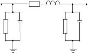
Ask a Question“DC motors are large. But they can be connected according to a relatively simple scheme, which will provide smooth speed control.
Assembly order
This algorithm explains the sequence of actions when working with the above drawings. Using other design documentation implies making appropriate changes to the assembly process.
Starting with the front headstock. Install the spindle in it. Next, the entire assembly using bolting is connected to the running pipe. Preliminarily, threads are cut on the fastening parts. When performing this operation, the alignment of the parts is carefully controlled.
At the next stage, a power frame is assembled from the channels. When the frame is made, the headstock is installed on it. Here you also need to carefully control the parallelism of the running tube and the long parts of the frame. Mark up accurately. Holes are drilled sequentially with an additional reamer bore, checking each attachment point. One or two errors will not unduly compromise the strength of the channel, so it is better to make a new precise hole in a different place, if necessary.
Note! Do not forget to install spring steel washers, which ensure the reliability of bolted connections in high vibration conditions.

When assembling this assembly, special attention should be paid to the accuracy of the placement of the central axes of the spindle (1) and quill (2). If a mistake is made, conical surfaces will be obtained instead of cylindrical when machining workpieces. Also check the parallelism of these elements of the running pipe. The support bar (3) prevents the tailstock from turning. Steel spacers can be used for height adjustment.
The caliper parts are installed sequentially in accordance with the assembly drawing diagram. Here especially high accuracy not needed as there are numerous adjustments. If heavy use is expected, make individual assemblies split so that wear parts can be replaced at no extra cost.
At the final stage, an electric motor is installed, connected to the mains according to the selected scheme. They check the functionality of the lathe for metal with their own hands in practice. For improvement appearance and corrosion protection, some parts are coated with a primer and paint.

How to make a lathe from a drill with your own hands
For, plastic, and other soft materials, the power of a typical household-level power tool is enough. This example shows how to make a functional machine with your own hands in 15-20 minutes. With the help of the latest photos in the table, the creation of an improved design is described:
| A photo | Assembly sequence with author's recommendations |
|---|---|
 | A serial drill was used as a basis. Processing of rather small preparations is supposed. For the bed, in this case, a sheet of plywood is selected, which is fixed on the table. Any other sufficiently strong and even base will do. |
 | It is necessary to securely fasten the power tool in a convenient position so as not to spoil it during operation. This problem can be solved with the use of an auxiliary body. It is made of thick plywood (20 mm), taking into account the appropriate overall dimensions. |
 | Separate parts of the structure are fastened with self-tapping screws. An element with a figured cutout is installed in the front part. This seat is created with a shape and dimensions that are suitable for mounting the protruding part of the solid body of the drill (marked with arrows). |
 | The base is screwed to the tabletop in the right place. Power tools are installed inside. For rigid fixation, a clamp is used. As a support bar, a wooden plate is fixed nearby. |
 | The cutter can be made from an old file. A standard grinder is suitable for processing this workpiece. |
 | A strong steel bar is inserted into the cartridge. A piece of wood is screwed onto it. |
 | Next, check the performance of the machine. |
 | If the cutter removes a small thickness with each pass, it will be possible to process workpieces from fairly hard materials. The finish surface is created using sandpaper. |
 | For processing larger workpieces, you can create a machine with a headstock and a tailstock. The photo shows the main elements of the structure. The power tool is fixed securely, but, if necessary, it can be removed for use for its intended purpose. |
 | A support with a metal insert (handguard) is installed here, which helps to accurately and accurately move the cutter. |
Video: lathe in 15 minutes
Features of creating a lathe for metal with your own hands
The previous chapter talked about the simplest designs that will help you make a lathe from a drill using inexpensive improvised materials. In some cases, even detailed drawings will not be needed. This approach is sufficient when working with wooden blanks, when high accuracy is not needed.
Related article:
But it will not work if you need to create a metalworking lathe with your own hands. The video demonstrates not only the potential quality equipment this category, but also the tasks solved by the author of the project:
How can you independently upgrade a lathe
The drawings discussed above are a time-tested project. With their help, you can make a functional mini lathe for metal with your own hands. But some modern improvements will be appropriate:
- The belt drive should be covered with a casing to prevent potential danger.
- For an emergency shutdown of the power supply, a special button is installed in a conspicuous place (at a distance of close accessibility).
- Instead of a grate, a protective screen made of a transparent polymer is used.
- The incandescent lamp is changed to an economical, mechanically resistant LED lamp.
- Automata (sensors, fuses) are installed in the power circuit of the electric motor, which prevent overheating and other emergencies.
- The frame is mounted on damping pads, reducing the level of noise and vibration.
- The driving chuck is changed to a more convenient three-jaw version, which automatically centers the workpiece during the clamping process.
- Clamping in the grinding wheel chuck expands the possibilities of processing.
Note! To create a high-quality milling machine with your own hands for metal, you need to apply other design solutions.
Features of work on homemade lathes


Mastering metal processing is a topic for a separate article. To obtain the desired result, take into account the viscosity and brittleness, other characteristics of the metal and working edges. The technology is optimized taking into account the speed of rotation of the workpiece, the temperature regime.

Video of metal lathes (advice from an experienced craftsman):
Safety precautions when working with a homemade lathe and proper care
After assembly, it is necessary to make sure that there are no malfunctions before connecting to the network. Check the free rotation of the spindle, the absence of delays in the operation of drive mechanisms and extraneous noise. Accuracy is carefully controlled. It is necessary that the parameters of the power network correspond to the needs of the power unit in the mode of greatest power consumption, when turned on.
Before starting work, make sure the presence (serviceability) of protective screens, casings. A new tool is installed with the motor stopped using all standard fasteners. Observe the processing modes corresponding to the parameters of the cutters and the workpiece.
After completion of work operations, waste is removed. Timely perform lubrication and other work provided for by the maintenance regulations.
Metal lathe market offers: varieties, prices, additional equipment
| Brand / Model | Length* Width* Height, cm / Weight, kg | Power consumption, W | Price, rub. | Notes | |||
|---|---|---|---|---|---|---|---|
 Jet/ BD-3 | 50*30*39/ 16 | 260 | 31500− 33400 | Miniature metal lathe for the home workshop. Three-jaw chuck (50 mm). Turning diameter - up to 100 mm. Optional equipment with longitudinal feed. |
44
590 | 55200− 57600 | Semi-professional metal lathe. Smooth adjustment of the spindle speed (100-3000 rpm). Threading gears as standard. |
 Kraton/ MML-01 | 69,5*31*30,5/ 38 | 500 | 51300− 54600 | Spindle speed - from 50 to 2500 rpm. Workpiece dimensions: up to 180*300 mm. |
|||
Kraton MML-01 |
|||||||
Kraton MML-01
You should carefully evaluate the process of creating a homemade lathe with your own hands. Taking into account real costs, it may turn out to be less economical than purchasing a finished product. Accurate conclusions can be drawn only taking into account real conditions. In any case, the personal implementation of the project implies the potential possibility of creating equipment with unique technical characteristics.

Save Time: Featured Articles Every Week by Mail
DIY do-it-yourself metal lathe: drawings, photos,
Many home craftsmen are thinking about how to make a metal lathe on their own. This desire is explained by the fact that with the help of such a device, which will cost quite inexpensively, you can effectively perform a large list of turning operations, giving metal blanks the required size and shape. It would seem that it is much easier to purchase the simplest desktop machine and use it in your workshop, but given the considerable cost of such equipment, it makes sense to spend time making it yourself.
Homemade lathe - it's quite real
Using a lathe
The lathe, which was one of the first to appear in the line of equipment for processing parts from different materials, including from metal, allows you to manufacture products various forms and sizes. With the help of such a unit, it is possible to turn the outer and inner surfaces of the workpiece, drill holes and bore them to the required size, cut external or internal threads, perform knurling in order to give the surface of the product the desired relief.
A serial metal lathe is a large-sized device that is not so easy to manage, and its cost is very difficult to call affordable. It is not easy to use such a unit as a desktop equipment, so it makes sense to make a lathe for your home workshop yourself. Using such a mini-machine, you can quickly turn workpieces made not only from metal, but also from plastic and wood.
On such equipment, parts are processed that have round section: axles, tool handles, wheels, structural elements of furniture and products for any other purpose. In such devices, the workpiece is located in a horizontal plane, while it is given rotation, and the excess material is removed by a cutter, securely fixed in the machine support.

Grooving a brake disc on a homemade lathe
Despite the simplicity of its design, such a unit requires a clear coordination of the movements of all working bodies so that the processing is carried out with the utmost precision and the best workmanship.
An example of a homemade lathe with drawings
Let us consider in more detail one of the working options of the assembled on your own lathe, the rather high quality of which rightfully deserves the closest attention. The author of this homemade product did not even stint on the drawings, according to which this device was successfully manufactured.
Of course, not everyone needs such a thorough approach to business, often simpler structures are built for home needs, but as a donor for good ideas this machine fits perfectly.

DIY lathe
Structural knots
Any, including home-made, lathe consists of the following structural elements: a supporting frame - a bed, two centers - a leading and a driven one, two headstocks - front and rear, a spindle, a caliper, a drive unit - an electric motor.

The design of a small-sized lathe about metal
All elements of the device are placed on the bed; it is the main bearing element of the lathe. The headstock is a fixed structural element on which the rotating spindle of the unit is located. In front of the frame there is a transmission mechanism of the machine, with the help of which its rotating elements are connected to the electric motor.
It is thanks to this transmission mechanism that the workpiece receives rotation. The tailstock, unlike the front, can move parallel to the direction of processing, with its help the free end of the workpiece is fixed.

simple circuit nodes of a home-made machine for wood will tell you a simple option for making a bed, front and rear headstock
A home-made metal lathe can be equipped with any electric motor, even if it is not too high power, but such an engine can overheat when processing large-sized workpieces, which will lead to its stop and, possibly, failure.
Usually, electric motors are installed on a homemade lathe, the power of which is in the range of 800–1500 watts.
Even if such an electric motor has a small number of revolutions, the problem is solved by choosing the appropriate transmission mechanism. To transmit torque from such electric motors, belt drives are usually used; friction or chain mechanisms are very rarely used.
Mini-lathes that home workshops are equipped with may not even have such a transmission mechanism in their design: the rotating chuck of the unit is fixed directly on the motor shaft.

Direct drive machine
There is one important rule: both centers of the machine, leading and driven, must be located strictly on the same axis, which will avoid vibration of the workpiece during its processing. In addition, it is necessary to ensure reliable fixation of the part, which is especially important for models of the frontal type: with one leading center. The issue of such fixation is solved with the help of a cam chuck or a faceplate.
In fact, a do-it-yourself lathe can also be made with a wooden frame, but, as a rule, metal profiles are used for these purposes. The high rigidity of the frame of the lathe is necessary so that the accuracy of the location of the leading and driven center is not affected by mechanical loads, and its tailstock and support with the tool move freely along the axis of the unit.

The use of channels in the manufacture of the frame and headstock of the machine
When assembling a lathe for metal, it is important to ensure that all its elements are securely fixed, always taking into account the loads to which they will be subjected during operation. What dimensions your mini-machine will have, and what structural elements it will consist of, will be influenced by the purpose of the equipment, as well as the size and shape of the workpieces that are planned to be processed on it. The power of the electric motor that you will need to use as a drive will also depend on these parameters, as well as on the planned load on the unit.

Version of the bed, headstock and drive
To equip lathes for metal, it is not recommended to choose commutator motors that differ in one characteristic feature. The number of revolutions of the shaft of such electric motors, as well as the centrifugal force that the workpiece develops, increase sharply with a decrease in load, which can lead to the part simply flying out of the chuck and can seriously injure the operator.
Such electric motors can be used if you plan to process medium-sized and light parts on your mini-machine. But even in this case, the lathe must be equipped with a gearbox that will prevent the uncontrolled increase in centrifugal force.

Asynchronous three-phase electric motor connected to a 220 Volt network through a capacitor
It has already been proven by practice and design calculations that for turning units on which metal blanks up to 70 cm long and up to 10 cm in diameter will be processed, it is best to use asynchronous electric motors power from 800 watts. Engines of this type are characterized by the stability of the rotational speed in the presence of a load, and when it is reduced, it does not increase uncontrollably.
If you are going to make a mini-machine for turning metal work on your own, then you should definitely take into account the fact that not only transverse, but also longitudinal loads will affect its cartridge. Such loads, if not provided for by a belt drive, can cause destruction of the motor bearings, which are not designed for them.
If it is not possible to use a belt drive, and the leading center of the device is directly connected to the motor shaft, then a number of measures can be taken to protect its bearings from destruction. Such a measure can be a stop that limits the longitudinal movement of the motor shaft, which can be used as a ball installed between the motor housing and the rear end of its shaft.
In the tailstock of the lathe, its driven center is located, which can be stationary or freely rotate. The most simple design has a fixed center: it is easy to make it on the basis of a conventional bolt, sharpening and grinding to a cone that part of it that will be in contact with the workpiece. By screwing in or unscrewing such a bolt moving through a threaded hole in the tailstock, it will be possible to adjust the distance between the centers of the equipment, thereby ensuring a secure fixation of the workpiece. Such fixation is also provided by moving the tailstock itself.
In order for the workpiece to rotate freely in such a fixed center, the pointed part of the bolt that comes into contact with it will need to be lubricated with machine oil before starting work.

Homemade tailstock for a desktop lathe
Today it is not difficult to find drawings and photos of lathes, according to which you can independently manufacture such equipment. Moreover, it is easy to find various ones that demonstrate the process of their manufacture. It can be a mini-CNC machine or a very simple device, which, nevertheless, will give you the opportunity to quickly and with minimal labor to produce metal products of various configurations.
Racks of the simplest metal lathe can be made of wood. They will need to be securely fastened to the frame of the unit using bolted connections. The frame itself, if possible, is best made from metal corners or a channel, which will provide it with high reliability, but if they are not at hand, you can also pick up thick wooden bars.
Below is the process self-manufacturing support for a lathe.
As a node on such a machine, on which the cutting tool will be fixed and moved, a handguard made of two wooden planks connected at an angle of 90 degrees will act. On the surface of the board where the tool will be placed, it is necessary to fix a sheet of metal that will protect the wood from deformation and ensure the exact location of the cutter in relation to the workpiece. In the supporting surface of a horizontal plank moving along the frame of the unit, it is necessary to make a slot, due to which such movement will be sufficiently accurate.
For the manufacture of the headstock and tailstock of your homemade lathe, it will be necessary to select metal cylinders of the appropriate size, which are placed in bearing assemblies installed in wooden racks. The rotation made by the workpiece will be transmitted to it through the front center, connected by a belt drive to the electric motor. Thus, the workpiece, securely fixed between the front and rear center, is processed using a cutter installed in the tool rest of the equipment.

Another option for a homemade machine (click to enlarge)
There should be no problems with the search for an electric motor, which should be equipped with a mini lathe. Even if you could not find an engine of the required power (500–1000 W for processing small parts, 1500–2000 W for large-sized workpieces), then a previously used unit previously installed on a household sewing machine is quite suitable. In addition, it is permissible to use electric drills or grinders as a drive for compact lathes.
As a result of such simple manipulations, you will have at your disposal a machine capable of performing the most common metal turning operations. If desired, the unit can be upgraded by expanding it functionality. Of course, it is difficult to make a CNC machine from such a device, but it is quite possible to perform boring, drilling, grinding, threading and a number of other technological operations on metal on it.
https://met-all.org
legkoe-delo.ru
DIY do-it-yourself metal lathe: manufacturing and operation
A lathe is needed for the manufacture and processing of metal parts. Professional equipment is quite expensive, so in order to save money, you can make a home-made metal lathe with your own hands. This can be done in several ways, and drawings of such a product are easily found on the Internet. You can use improvised materials for manufacturing, but the size of the machine can be any.

A professional lathe has a high cost, so it makes sense to make such a device yourself
- 1 Components of a mini-lathe for metal with your own hands
- 1.1 Do-it-yourself lathe support: drawings, how to make from improvised materials
- 2 Do-it-yourself homemade metal lathe: assembly procedure
- 3 Choosing an electric motor for the machine
- 4 Making a lathe from a drill with your own hands
- 5 Features of the work of metal lathes with your own hands, video instructions as a way to avoid mistakes
- 6 Safety precautions when working with a homemade lathe
- 7 Options for upgrading a homemade lathe
Components of a mini-lathe for metal with your own hands
Any homemade lathe consists of the following elements:
- drive - the main part of the mechanism, which is responsible for its power. Choosing a drive with the required power is one of the most difficult tasks. In small lathes for metal with your own hands, you can use a drive from a conventional washing machine or drill. Usually, the power of this element starts from 200 W, and the number of revolutions per minute - from 1500;
- bed - the supporting frame of the structure, which can be made of wooden bars or a steel corner. The bed must be characterized by high strength, otherwise the whole structure may fall apart from vibrations during operation;

Projection and main components of a lathe for metal
- tailstock - made of a steel plate and a steel corner welded to it. The plate rests against the guide beds, and the main purpose of the tailstock of the lathe with your own hands is to fix the metal part during processing;
- headstock - a part similar to the tailstock, but mounted on a movable frame;
- leading and slave centers;
- caliper - a thrust mechanism for the working part.
Torque from the engine to the working part of the machine can be transmitted in several ways. Someone prefers to directly install the working part on the motor shaft - this saves space and allows you to save on spare parts. If this option is not possible, the torque can be transmitted using a friction, belt or chain drive. Each of these options has its own advantages and disadvantages.
A belt drive for an electric motor is the cheapest and is characterized by a fairly high level of reliability. For its manufacture, you can use a belt for an electric motor, removed from any other mechanism. The disadvantage of a belt drive is that over time the belt can wear out and will have to be changed more often the more intensively you work with the machine.

The device of the front and rear headstock of a lathe. Headstock (left): 1 - wedge-shaped belt; 2 - two-stage pulley; 3 - spindle; 4 - ball bearing. Tailstock (right): 1 - body; 2 - center; 3, 6 - handles; 4 - quill; 5, 12, 14 - screws; 7 - flywheel; 8 - thrust; 9, 10 - levers; 13 - nut
A chain drive is more expensive and takes up more space, but will also last much longer than a belt drive. Friction transmission has intermediate characteristics between belt and chain.
Do-it-yourself lathe caliper: drawings, how to make from improvised materials
The caliper is one of the most important parts of a homemade lathe - the quality of the future part depends on it, as well as the amount of time and effort that you spend on its manufacture. This part is located on a special sled that moves along the guides located on the bed. The caliper can move in three directions:
- longitudinal - the working part of the machine moves along the workpiece. Longitudinal motion is used to turn a thread into a part or to remove a layer of material from the surface of a metal workpiece;

DIY metal lathe
- transverse - movement perpendicular to the axis of the workpiece. Used for turning recesses and holes;
- oblique - movement at different angles for turning recesses on the surface of the workpiece.
When making a lathe caliper with your own hands, it is worth considering the fact that this part is subject to wear as a result of vibrations that occur during operation. Because of them, the fasteners are loosened, there is a backlash, all this affects the quality of the manufactured part. In order to avoid such problems, the caliper must be regularly adjusted and adjusted.
Do-it-yourself adjustment of a home-made caliper for a lathe is carried out according to gaps, backlash and oil seals. Clearance adjustment is needed when the screw responsible for moving the part in the longitudinal and transverse planes has worn out. As a result of friction, the caliper begins to loosen under loads, which significantly reduces the accuracy of manufacturing the part. You can eliminate the gaps by inserting wedges between the guides and the carriage. The backlash of the part is eliminated with a fixing screw.
If the oil seals are worn out in your machine, they should be thoroughly washed and soaked with fresh machine oil. In case of critical wear, it is better to completely replace the seals with new ones.

Caliper device: 1 - caliper carriage; 2 - lead screw; 3 - cross slide of the caliper; 4 - the rotary part of the caliper; 5 - guides of the rotary part; 6 - tool holder; 7 - screw for fixing the tool holder; 8 - screws for fixing the cutters; 9 - handle for turning the tool holder; 10 - nuts; 11 - the upper part of the caliper; 12 - transverse guide carriages; 13 - handle for moving the upper part of the caliper; 14 - handle for moving the cross slide; 15 - handle for turning on the supply of the caliper from the lead screw; 16 - handwheel for longitudinal movement of the caliper; 17 - apron
Do-it-yourself homemade lathe for metal with your own hands: assembly procedure
The mechanism is assembled in the following order:
In addition, according to the do-it-yourself drawings of a metal lathe, it can be seen that a handpiece is made to increase the stability of the cutting mechanism, and a thin strip of metal is fixed on the lower part of the structure. The latter serves to protect the working part of the machine from deformation during operation.

The device of a home-made lathe for metal processing: 1, 7 - channels; 2 - running pipe; 3 - tailstock; 4 - pallet for collecting chips; 5 - support; 6 - lead screw; 8 - electric motor; 9 - fixed headstock; 10 - lamp in a protective cap-reflector; 11 - mesh screen to protect the turner from chips; 12 - support
Choosing an electric motor for a machine
The most important part of a homemade metal lathe, the video of which can be easily found on the Internet, is the electric motor. It is with its help that the movement of the working part of the machine is carried out. Accordingly, the power of the entire structure depends on the power of this mechanism. It is selected depending on the size of the metal blanks with which you plan to work.
If you plan to work on a machine with small parts, a motor with a power of up to 1 kW is quite suitable for this. It can be removed from an old sewing machine or any other similar electrical appliance. To work with large parts, you will need an engine with a power of 1.5-2 kW.
When assembling a homemade metal lathe according to ready-made drawings, keep in mind that all electrical parts of the structure must be securely insulated. If you do not have the necessary experience with electrical equipment, it is better to seek help from a specialist in connection. So you will be sure of the safety of work and the reliability of the design.

The asynchronous motor is the best option for homemade lathe
Making a lathe from a drill with your own hands
If you want to save on spare parts and greatly simplify the task of assembling a homemade lathe, you can use a conventional electric drill as a drive. This design solution has a number of advantages:
Of course, there are also negative sides to a lathe from a drill. How to make processing large parts possible with this tool? This is practically impossible, since the drill has a relatively small torque and a large number of revolutions. Of course, you can increase these parameters if you still install a belt drive and use it to transmit torque from the drill to the spindle, but this will greatly complicate the design, the main advantage of which is simplicity and compactness.

Diagram of a homemade lathe based on a drill: 1 - fastening to a table or workbench; 2 - front support; 3 - support for the workpiece; 4 - rear support
Making a homemade desktop metal lathe based on a drill makes sense in cases where you do not need to carry out large-scale work, and only small details need to be turned.
To make a metal lathe based on an electric drill, you will need the same parts as for a conventional design, with the exception of an electric motor and a headstock. The role of the latter is also performed by a drill. Given the compactness of the design, an ordinary table or workbench can be used as a bed, on which all components of the machine will be fixed. The drill itself is fixed in the structure with a clamp and a clamp.
Using a homemade lathe, you can not only grind parts, but also apply paint to a rotating workpiece, wind wire on a transformer, make spiral notches on the surface of a part, and perform many other actions. In addition, if you assemble a copier attachment for the machine, then with its help you can quickly and effortlessly produce small identical parts.

Drawing of the front support, inside which the drill is fixed
Features of the work of lathes for metal with their own hands, video instructions as a way to avoid mistakes
Like any other equipment, homemade lathes have their own characteristics that must be considered during assembly and operation. For example, when working with large parts or when using a powerful electric motor, strong vibrations occur, which can lead to serious errors in the processing of the part. To get rid of vibrations, the leading and driven centers of the machine must be installed on the same axis. And if you plan to install only the leading center, a cam mechanism should be attached to it.
In do-it-yourself desktop lathes for metal, it is not recommended to install a commutator motor. It is prone to a spontaneous increase in the number of revolutions, which can lead to the departure of the part. This, in turn, can lead to work injury or property damage. If, however, it is impossible to do without installing a collector motor, it is imperative to install a gearbox with it to lower the speed.
The ideal motor option for a homemade lathe is asynchronous. It does not increase the speed during operation, is resistant to heavy loads and allows you to work with metal blanks with a width of up to 100 mm.

The most important thing when working on a lathe is safety
The rules for installing and operating any type of electric motor for a lathe can be viewed in numerous video instructions on the Internet. With their help, you will not only avoid common assembly errors, but also save time and effort due to the visibility of the material.
Safety precautions when working with a homemade lathe
When working with the structure, certain safety precautions must be observed. So, after assembling the machine, you need to check its performance. The spindle should rotate easily and without delay, the front and rear centers must be aligned on a common axis. The center of symmetry of a rotating part must coincide with its axis of rotation.
On any video of the lathe with your own hands, you can see that after mounting the electric motor, it is covered with a special casing. The latter serves not only to protect the operator of the machine, but also to protect the motor itself from dust, metal particles and dirt. For a machine made on the basis of an electric drill, such a casing is not needed.

An example of a do-it-yourself metal lathe
You should also adhere to the following safety rules:
Options for upgrading a homemade lathe
If you need a mechanism that can not only perform turning work, but also grind and paint the workpiece, the basic machine can be easily modified. It is best to do this for a design based on an electric drill, since it is easiest to replace the working part in it.

The lathe can be a multifunctional device in the workshop, with which you can perform various tasks, including household ones: sharpening knives, scissors, etc.
There are several popular modifications of the lathe for metal. How to make a conical hole? To do this, two files must be attached to the base so that they form a trapezoid. After that, a spring mechanism is mounted, which ensures that the files are fed forward and at an angle, which allows drilling cone-shaped holes into the part.
In addition, to work with metal parts of different lengths, you can make a machine with a collapsible base. With the help of several boards or metal corners, you can bring the working tool closer or further away from the fasteners that hold the part, as well as change the size of the gap between the fasteners. It is most convenient to make such a design on the basis of a conventional table or workbench.
If you attach a grinding wheel to the electric motor as a working tool, you can use the machine not only to polish the surface of the part, but also to sharpen knives, scissors and other household tools. Thus, the lathe turns into a convenient multifunctional mechanism.

Creating a lathe with your own hands will allow you to get equipment that is optimally suited to the needs of the owner
Assembling a lathe at home is a fairly simple task, which is further simplified by numerous video instructions and drawings from the Internet. At the same time, you can literally assemble the structure from improvised parts, using old household appliances and waste from assembly and construction production.
The main advantage of self-assembly is cost savings. In addition, it is worth noting the ability to independently adjust the dimensions and power of the device in order to adapt it to your needs. A home-made machine can be not only large, but also quite miniature, designed for processing small parts.
ibuildrussia.ru
How to assemble a lathe for metal with your own hands
 A lathe is necessary for the production and processing of metal parts. Factory devices cost a lot of money. That is why, for greater savings, it is worth making a lathe with a cutter to process iron with your own hands. You can quickly assemble it in several ways, and high-quality drawings and videos are worth looking for on the net. Any available materials can be used for assembly, and the dimensions of the machine depend on production needs.
The main components of a small lathe
A high-quality do-it-yourself lathe always consists of the following parts:

The torque from the electric motor to the working part of the device can be transmitted in several ways. Some people directly put the working part on the axis of the electric motor. This method will help save space and the number of spare parts for the machine. When this method cannot be implemented, then the torque should be transmitted using different types gears. Each of these methods has advantages and disadvantages.
The belt drive for the engine is considered the cheapest and has good reliability. To make it, you need to use a belt for the engine, which is removed from another product. The main disadvantage of a belt drive is that after some time the belt frays and will need to be replaced. The frequency of replacement depends on the intensity of the machine.
A chain drive often takes up a lot of space and is very expensive. Its service life is much longer than that of a belt mechanism. And the friction transmission is characterized by average characteristics, in contrast to the chain and belt mechanism.
A good do-it-yourself caliper for a metal lathe: drawings
The caliper can be considered the most important part of a do-it-yourself machine, because it is he who affects the quality of the workpiece, the amount of effort and the length of time spent on its manufacture. Such a part is placed on a specialized sled that moves along the guides installed on the fixture frame. The caliper is able to move in the following directions:
- Longitudinally, when the entire working part of the device and the cutter moves along the workpiece. Such a movement is used to make a thread in a workpiece or when removing a small layer from the surface of a metal product.
- Transverse, when the movement of the cutter occurs perpendicular to the working axis of the workpiece. This movement is used for precise turning of holes and various recesses.
- Oblique, when the movement of the cutter occurs at different angles. This motion is often used to make small indentations in a workpiece.
In the manufacture of the caliper of a small home-made machine, it must be taken into account that this part is subject to wear due to strong vibration during operation. As a result, the fasteners are often loosened and a backlash appears between them, which affects the quality of the workpiece being processed. To avoid such problems, the caliper needs to be adjusted and tuned frequently.
Adjustment of the caliper of a small machine is carried out by backlash, gaps and several seals. Such work must be done when there is wear on the screw, which is responsible for the movement of the part in the transverse as well as in the longitudinal plane. Due to the high friction, the caliper can loosen under heavy loads, and this reduces the accuracy of the workpiece. It is necessary to eliminate backlashes by installing wedges between the carriage and special guides. A small gap in the workpiece can be eliminated using a special fixing bolt.
When oil seals wear out in a homemade machine, they should be washed well and treated with high-quality lubricant. With a lot of wear, the seals must be replaced with new parts.
How to assemble a good mini metal lathe with your own hands
Making a good machine to process iron with your own hands is always done in this order:

And also according to numerous drawings, it is clear that in order to increase the stability of the cutter mechanism, it is necessary to make a specialized handpiece, and at the bottom of the product it is worth installing a small iron strip. This strip is necessary for reliable protection of the working units of the device from damage during the processing of workpieces.
How to choose a motor for a homemade metal machine
The most important part of the lathe, whose assembly photos and videos can be found on the net, is the electric motor. With its help, the working part of the product moves. Thus, the maximum power of the machine depends on the power of this part. This indicator must be chosen depending on the dimensions of the iron blanks that will be processed in the future.
When you need to process small workpieces on a lathe, then an electric motor with a maximum power of up to 1.4 kilowatts is enough for it, which can be taken with a simple sewing machine or other electrical device. To work with large workpieces, you need an electric motor with a power of up to 2 kilowatts.
When making a small lathe using videos or drawings, you need to consider that all electrical components of the device must be well insulated. When there is not much experience with such equipment, it is worth seeking help from a qualified specialist. This can ensure the safety of the assembly and the reliability of the fixture.
How to quickly assemble a homemade metal lathe from a drill
When you need to save on spare parts and just make it easier to make a device with your own hands, you can use a simple electric drill instead of a drive. Such a method has the following advantages:
- Production takes little time, because the drill is very simply attached to the machine bed.
- Transporting a homemade machine is very easy, because it is often necessary to work with iron parts outdoors or indoors.
- Big savings, because the electric drill not only replaces the engine, but also eliminates the need for a gear. Additionally, you can use various nozzles instead of many types of tools.
There are also some drawbacks to homemade device from a drill. It is quite difficult to process large workpieces with such a desktop machine, because the electric drill has a small torque and a large number of revolutions. And you can also increase the power of the machine if you put a belt drive. With its help, torque will be transmitted from the electric drill to the shaft. However, this will greatly complicate the device, the advantage of which is compactness and simplicity.
Assembling the machine using an electric drill is advisable in cases where you do not need to process large parts, but only small workpieces are machined.
To assemble a similar product, the same parts will be needed as for standard model except for the headstock and engine. The drill will replace the electric motor. Due to the compactness of the machine, the bed can be a workbench or a simple table on which all the details of the device will be fixed. The electric drill is attached to the product with a clamp and a metal clamp.
With the help of such a lathe, it is possible not only to manufacture various parts, but also to paint blanks, wind wire on a transformer, apply spiral notches to the surface of products, and perform other necessary actions. And also if you make a special attachment for the machine, then it will be possible to easily produce small identical products.
Metal lathes


Components of a home unit
It usually contains the following constituent elements:
- a bed, which is the supporting frame of the entire structure, which must be particularly strong so as not to break during vibration during its operation;
- drive, which is the main part of the mechanism, responsible for the power of its action (you can use the drive of a drill or washing equipment);
- tailstock made of a steel plate element with a steel corner welded to it for fixing metal products when working on this unit;
- headstock, similar to the tailstock, only mounted on the moving part of the frame structure;
- driven and leading centers on the tailstock;
- caliper, which serves as a thrust mechanism in the operating part of the unit.
The structure of the lathe
- torque to the working part of the device from the engine can be produced different ways, for example, install the working part on the motor shaft itself or use a friction, belt or chain drive;
- to install a belt drive, which is quite inexpensive with a fairly high level of reliability, it is quite possible to use a belt removed from the electric motor of another device (just remember that the belts wear out over time and must be replaced frequently);
- installing a chain drive will be more expensive, take up more space, but it will last longer than a belt drive;
- when installing a friction transmission, it is important to understand that its characteristics correspond to intermediate data between the action of a chain and a belt drive.
Machine device
If we consider the drawing of a home turning device, then it is obvious that its headstock consists of the following elements:
- V-belt;
- two-stage pulley;
- spindle
- ball bearing.

The tailstock in a lathe contains the following parts:
- frame;
- center;
- two handles;
- pinole;
- three screws;
- flywheel;
- thrust;
- lever arm;
- screw.
It must be borne in mind that the driven center is located on the tailstock and can be either dynamic or stationary. Such a center can be made from a simple bolt, sharpened at one end, giving a conical shape. They are treated with technical oil (solid oil), inserted inside.
The tailstock is made in a similar way, using the same cone-shaped bolt with a lock nut.
Homemade metal lathe
caliper
This part of the device, which serves as an emphasis for the working surface, is located on moving, along specially placed guides, “sled”. The caliper generally moves in three specific directions:
- longitudinal, for moving the working part of the machine along the workpiece used to carve threads in parts, chamfer;
- transverse, used for turning all kinds of holes, recesses, recesses;
- inclined, produced at different angles, also used for turning different recesses on the surface of workpieces.
If you look at the drawing of the caliper, you can see that it includes the following details:
- cross slide;
- lead screw;
- guides;
- cutter holder;
- screw for its fastening;
- carriage;
- turning part;
- handle for turning the tool holder;
- handle for moving the upper part;
- upper part of the caliper;
- flywheel for longitudinal movements;
- nuts;
- handle for moving the sled;
- apron;
- transverse guides;
- handle to turn on the feed from the lead screw.
To make a caliper yourself, you need to take into account that it is subject to significant wear due to the vibration that occurs during its operation. As a result, the fasteners can loosen, play appears, which does not contribute to good quality parts manufactured on it. To avoid such troubles, it is recommended that the caliper be constantly adjusted and adjusted.
A few tips for setting up the machine caliper:
- it becomes necessary to adjust the gaps if the screw, which is responsible for movement in the longitudinal and transverse planes, has worn out;
- due to the resulting friction, the caliper may begin to stagger under loads, which leads to a decrease in the accuracy of manufactured parts;
- to eliminate the resulting gaps between the guides, you can insert wedges;
- to eliminate backlash in parts, a fixing screw is usually used;
- in case of severe wear of the oil seals, they must be washed well, then soaked with fresh technical oil, and if necessary, replaced with new ones.

If all the operations performed to restore the oil seals did not help, you will have to purchase new ones.
Self-assembly of the machine
If we consider the assembly drawing of a home turning device, we can see that it includes the following parts:
- tailstock;
- running pipe;
- channels;
- caliper;
- a pallet designed to collect chips;
- electric motor;
- lead screw;
- headstock;
- lamp in a special protective cap;
- support;
- chip screen.

To build a mini-lathe with your own hands, you need to follow a certain order:
- make the frame of the device out of metal beams, and it is desirable that the thickness of the material used be at least 3 mm for corners and at least 30 mm for rods;
- install special longitudinal shafts on the channels by welding them or fixing them with bolts;
- make a headstock using a hydraulic cylinder with a wall thickness of at least 6 mm (2 bearings must be pressed into the cylinder);
- lay the shaft using bearings of a slightly larger diameter;
- then fill the hydraulic cylinder with lubricating fluid;
- install the drive.
Such a miniature lathe, made independently, can serve not only for turning purposes, but even perform grinding and polishing operations if a grinding wheel is attached to it.
Engine
One of the most important parts included in a do-it-yourself homemade metal lathe is an electric motor, with the help of which the working parts of the device can actually be moved.
In the case when it is supposed to perform turning work with small parts on the machine, the power of the electric motor can be small (up to 1 kW), it is convenient to remove the motor from an old-style electric sewing machine or use another similar electrical device.
If the machine is going to work with large parts, an electric motor with a power of 1.5 to 2 kW may be required.
When assembling such a machine yourself, you must make sure that all electrical parts of the assembled device are securely insulated.
Drill machine
To facilitate your work on arranging a home machine, you can take a simple electric drill for the drive.

Do-it-yourself lathe with a drill
Such a lathe from a drill has several advantages:
- this device can be assembled very quickly, and if necessary, disassembled (if the drill needs to be used for its intended purpose), then reassemble it;
- this lathe from a drill is compact, easy to carry, transported to any place (you can bring it to the garage, for example, or, conversely, take it outside);
- profitable and economical, since the drill replaces the electric motor, which means that there is no need to use the transmission;
- convenient, because replaceable drill bits can be used as necessary working tools.
The disadvantages of a lathe from a do-it-yourself drill include the inability to process large parts on it.
If a grinding wheel is attached to the electric motor of a manufactured lathe for metal, then knives, scissors and various household tools can be sharpened on it.