What is the total conductivity of the circuit. Conductance
Reactive conductivity is due to the presence of capacitance between phases and between phases and ground, since any pair of wires can be considered as a capacitor.
For overhead power transmission lines, the value of linear reactive conductivity is calculated by the formulas:
7.58×10 - 6 b 0 r lg D cf .
R pr eq
Splitting increases b 0 by 21¸33%.
For CLEP, the value of per unit conductivity is often calculated using the formula
b 0 =w× C 0 .
Capacitance value C 0 is given in the reference literature for various brands of cable.
The reactive conductivity of the network section is calculated by the formula:
B = b 0 × l.
For overhead power lines, the value b 0 is much less than that of cable transmission lines,
little, because D avg. overhead power lines >> D cf. KLEP.
Under the action of voltage, a capacitive current flows in the conductances (bias current or charging current):
I c= AT× U f.
The value of this current determines the loss of reactive power in reactive conduction or the charging power of the transmission line:
D Qc=Q charge = 3 × U × I c= B × U 2 .
In district networks, charging currents are commensurate with operating currents. At U nom = 110 kV, value Q c is about 10% of the transmitted active power,
at U nom = 220 kV - Q from ≈ 30% R. Therefore, it must be taken into account in the calculations. In a network with a rated voltage of up to 35 kV, the value Q can be neglected.
Power line equivalent circuit
So, the power line is characterized by active resistance R l, reactive sop-
opposing line X l, active conductivity G l, reactive conductivity AT l. In calculations, power lines can be represented by symmetrical P- and T-shaped circuits (Fig. 4.6).
| R | X | R/2 X/2 | X/2 | |
| R/2 | ||||
| B/2 | G/2 | B/2 | ||
| G | B | |||
| G/2 | ||||

Figure 4.6 - Equivalent circuits of power transmission lines: a) P - shaped; b) T - shaped
P - figurative scheme is used more often.
Depending on the voltage class, one or another parameter of the complete equivalent circuit can be neglected (see Fig. 4.7):
VTL with voltage up to 110 kV (D R core » 0);
VTL with voltage up to 35 kV (D R core » 0, D Q c » 0);
CLEP voltage 35 kV (reactance » 0)
· CLEP with a voltage of 20 kV (reactance » 0, dielectric losses » 0);
CLEP with voltage up to 10 kV (reactance » 0, dielectric losses » 0, D Q c » 0).
| X | R | X | R | |||
| B/2 | B/2 | |||||
| a) | b) | |||||
| R | ||||||
| R | R | |||||
| G/2 | B/2 | B/2 | B/2 | B/2 | ||
| G/2 | ||||||
| in) | G) | e) |

Figure 4.7 - Simplified equivalent circuits for power lines:
a) VTL at U rated up to 110 kV;
b) VTL at U rated up to 35 kV; c) KLEP at U rated 35 kV;
d) KLEP at U rated 20 kV; e) KLEP at U rated 6-10 kV;
Lecture #5
Transformer Equivalent Circuit Parameters
13. General information.
14. Two-winding transformer.
15. Three winding transformer.
16. Two-winding transformer with a split winding of low voltage.
17. Autotransformer.
General information
At power plants and substations, three-phase and single-phase, two-winding and three-winding power transformers and autotransformers, and power single-phase and three-phase transformers with a split winding of low voltage are installed.
In the transformer abbreviation, the following information is sequentially (from left to right):
device type ( BUT- autotransformer, without designation - transformer);
the number of phases ( O- single-phase, T– three-phase);
The presence of a split low voltage winding - R;
· cooling system ( M– natural circulation of oil and air, D– forced air circulation and natural oil circulation, MC– natural air circulation and forced oil circulation, DC- forced circulation of air and oil, etc.);
the number of windings (no designation - two-winding, T- three-winding accurate);
The presence of a voltage regulation device under load (OLTC);
performance ( Z- protective G- lightning resistant At- improved, L
- with cast insulation);
specific area of application FROM– for auxiliary systems of power plants, AND- for the electrification of railways);
rated power in kVA,
winding voltage class (mains voltage to which the transformer is connected) in kV.
Double winding transformer
On electrical diagrams, a two-winding transformer is represented as follows (Fig. 5.1):
| In the windings, schemes are indicated | ||||||
| VN | unity of the windings (star, star with nu- | |||||
| lem, triangle) and the mode of operation of it - | ||||||
| trawls: | ||||||
| star - with an isolated neutral | ||||||
| HH | pour; | |||||
| star with zero - there is a connection | ||||||
| neutral connection with earth. | ||||||
| Figure 5.1 - Conditional image | In accordance with the accepted system | |||||
| double winding | my notation is abbreviation trans- | |||||
| transformer. | ||||||
| formatter TDN-10000/110/10 decoded | ||||||
| rovyvaetsya: three-phase transformer- |
ny, two-winding with forced air circulation and natural oil circulation and voltage regulation system under load. Rated power - 10000 kV∙A, high voltage winding voltage class
- 110 kV, low voltage - 10 kV.
In practical calculations, a two-winding transformer is most often represented by an L-shaped equivalent circuit (Fig. 5.2).
| U 1 | R t | X t | U 2 * |
| AT t | G t |

Figure 5.2 - L-shaped equivalent circuit of a two-winding transformer
X t = X in + X n * .
The active and reactive resistances of the transformer (longitudinal branch) are the sum of the active and reactive resistances of the higher voltage winding and the lower voltage winding brought to it:
R t = R in + R n*;
The transverse branch of the equivalent circuit is represented by the active G t and jet AT t conductivity. Conductivity is usually connected from the side of the primary winding: for step-up transformers - from the side of the low voltage winding, for step-down transformers - from the side of the higher voltage winding.
In such an equivalent circuit, there is no transformation, that is, there is no ideal transformer. Therefore, in the calculations, the secondary voltage U 2 * turns out to be reduced to the voltage of the primary winding.
Active conduction is due to active power losses in the steel of the transformer due to magnetization reversal and eddy currents, reactive conduction
- magnetizing power. In the calculations of the modes of the electrical network, the conductivity is replaced by a load equal to the idling losses.
The parameters of the transformer equivalent circuit are determined from two experiments
– idling and short circuit. In experiments, the following values are determined, which are indicated in the passport data of the transformer:
active power loss in idle mode D P x in kW;
active power losses in short circuit mode D P k in kW;
short circuit voltage U k, in %;
no-load current I x, in %.
The values of active and reactive resistances are found from the experience of a short circuit (Fig. 5.3). The experiment is carried out as follows: the low voltage winding is short-circuited, and such a voltage is applied to the higher voltage winding ( U k) so that the rated current flows in both.
| So | how | voltage | ||||||||||||
| I 1nom | short | closures | ||||||||||||
| I 2nom | much | less nominal | ||||||||||||
| U to | cash | voltage | ||||||||||||
| transformer, then | ||||||||||||||
| ri active power in | ||||||||||||||
| conductivity | practical | |||||||||||||
| skis are equal to zero. So | ||||||||||||||
| Figure 5.3 - Short circuit experience | the way | all losses | ||||||||||||
| active power in the mode | ||||||||||||||
| double winding transformer. | ||||||||||||||
| me short | closures | |||||||||||||
| go to heat the windings. Mathematically, this can be written: | ||||||||||||||
| D P=3× I 2 | × R. | (5.1) | ||||||||||||
| to | 1nom | t |

If in formula (5.1) the current value is written through the power and rated voltage of the higher voltage winding
Short circuit voltage U k is the sum of the voltage drop across the active U to a and reactive U to p resistances. We express them as a percentage of the rated voltage.
Voltage drop in the active resistance of the transformer:
| U | to a | 3× I | × R | |||||||||
| U | , % = | ×100 = | 1nom | t | ×100. | |||||||
| to a | U in nom | U in nom | ||||||||||
Substitute the value in the expression R t. We get:
| ×D P× U 2 | |||||||||||||||||
| 3× I | × R | 3× I | D P | ||||||||||||||
| U | , % = | 1nom | t | ×100 | = | 1nomk in nom | ×100 = | to | ×100. | ||||||||
| to a | |||||||||||||||||
| U in nom | U in nom × S number 2 | S nom | |||||||||||||||
Thus, the magnitude of the voltage drop in the active resistance, expressed as a percentage, is proportional to the losses of active power in the short circuit mode.
The expression for the voltage drop in reactance as a percentage is as follows
| U to r | |||||||||||||
| 3× I | × X | t | |||||||||||
| U | , % = | ×100 = | 1nom | ×100. | (5.2) | ||||||||
| to r | U in nom | U in nom | |||||||||||
From it we can find the value of the reactance of the transformer:
| X t = | U kr × U in nom | . | |||||
| × | 3× I 1 number | ||||||
Multiply and divide the resulting expression by U in nom:
| X t = | U kr × U in nom | × | U in nom | = | U kr × U in room 2 | . | ||||||||
| U in nom | 100× S nom | |||||||||||||
| × 3 | × I 1 number | |||||||||||||
In modern transformers, the active resistance is much greater than the reactive. Therefore, in practical calculations, it can be assumed that U to p ≈ U j. Then, the formula for calculating the inductive reactance of a transformer is:
| X | = | U to × U in 2 | nom | . | |||
| t | |||||||
| × S nom | |||||||
Transformers have voltage regulation devices (OLTC or PBV), which allow you to change the transformation ratios. Therefore,
rank U k (hence the value of the inductive reactance) depends on the branching of the on-load tap-changers or on-load tap-changers. In calculations of steady state conditions, this dependence is neglected. It is taken into account when calculating short-circuit currents when choosing automation devices and relay protection.
The conductivities of the magnetization branch are determined from the open-circuit test (Fig. 5.4), which is performed at rated voltage. In this mode, the transformer consumes power equal to no-load losses:
 I 2 = 0
Figure 5.4 - Experience of idling of a two-winding transformer.
| G | = | D P X | . | ||||
| t | |||||||
| U in 2 | |||||||
| nom | |||||||
D S x = D P x + j D Q X.
Active power losses are proportional to the active conductance of the transformer
D P x = U in 2 rooms × G t.
From here, the value of the active wire can be determined.
Reactive power losses are proportional to the reactance of the transformer:
D Q x = U in 2 rooms × B t.
Therefore, the value of the reactive conductivity of the transformer is equal to:
B t = D Q X.
U in room 2
The value of reactive power losses is proportional to the magnetizing current
| D Q x = 3× I m × U in nom f, | (5.3) |
where U nom f - phase rated voltage of the transformer.
The value of the no-load current is the sum of the magnetizing current Iμ and then in steel I become:
I x= Iμ+ I become.
Since the current in steel is about 10% of the magnetization current, expression (5.3) can be written:
D Q x » 3× I x × U in nom f.
In the passport data, the value of the no-load current is given as a percentage of the rated current. Therefore we can write:
Taking into account the obtained expression, the formula for calculating the reactive conductivity is:
B t = I x % × × S nom.
Active and reactive conductances are determined from the condition of equality of phase shift angles:
 When switching from a parallel connection of elements with active and reactive conductance to a series connection of elements with active and reactive resistances, one should use the relations
In general, an electrical circuit or part of it can be represented by equivalent circuits. If you select a section in the circuit that has two clamps, then it can be replaced with an equivalent two-terminal network. The two-terminal network in the diagram is depicted as a rectangle (Fig. 2.34, c), and if the two-terminal network is active (there are sources of emf in the circuit section), then it is designated A, if it is passive (there are no sources of emf) - P.
RESONANCE OF CURRENTS
In an electric circuit with parallel connection of branches with R (G), L (BL) and C (BC) (see Fig. 2.31, a), the current is determined by formula (2.58).
Of particular interest is the case when the inductive and capacitive reactances are equal to each other. Then the total conductivity of the circuit Y \u003d G, since B \u003d BL - BC \u003d 0, and the total current
has a minimum value and only active component I = Iа. Therefore cos = 1.
Currents in branches with conductivities BL and BC, taking into account (2.63)
i.e., they are equal in value (IL = IC) and can exceed the total current in the circuit by a factor of BL/G if ВL = ВС > G. The vector diagram of the currents for the considered case is shown in fig. 2.37.
The circuit mode with parallel connection of elements with R, L and C, when BL \u003d BC, and the currents in the branches with reactive conductances IL and IC are equal in value and can exceed the total current of the circuit, is called the current resonance mode. This mode is characterized by IL =IC > I, if BL = BC > G; Iа = min; , ; ; ![]() ;
; ![]() ,
, ![]() .
.

 In the current resonance mode, the circuit under consideration behaves with respect to the power source as if it consists only of elements with active conductivity. In fact, currents can flow in the parallel branches with L and C, even exceeding the total current flowing in the power supply. But these currents are always opposite in phase to each other (Fig. 2.37). This means that every quarter of the period there is an exchange of energy between the magnetic field of the inductive coil and the electric field of the capacitor, which is maintained by the voltage U of the power source.
In the particular case when the active conductivity G = 0, the total current I = GU = 0. The current IL = IC = BCU > 0 flows in a closed LC circuit.
The results of calculations of the length of the voltage and current vectors and the phase shift angles were used in the construction of the vector diagram of the electrical circuit (Fig. 3.28).
3.14. Conductivity in electrical circuits of sinusoidal voltage
When calculating the electrical circuits of a single-phase sinusoidal voltage, the concepts of active, inductive reactive, capacitive-reactive and full conductivity are used.
Branches of an electrical circuit containing only active resistance (Fig. 3.3) are characterized by active conductivity g. To calculate it, the formula is used
For a branch of an electric circuit containing an idealized inductive element (see Fig. 3.6), the concept of inductive reactive conductivity b L is introduced. Conductivity calculation
C x C
Branches of an electrical circuit containing coils replaced by a series connection of active and inductive resistances (see Fig. 3.12) are characterized by active g,
inductive reactive b L and total y conductivities. In this case, the following expressions are used to calculate them:
r 2 + x L 2 . |
||||||||
Branches of an electrical circuit containing capacitors, replaced by a series connection of active and capacitive resistances (see Fig. 3.16), are characterized by active g, capacitive reactive b C and total y conductivities. For
calculation g , b C , y formulas are used
where z is the total resistance of the branch.
y = 1 . |
||||||
Impedance z |
in this case, one should calculate |
|||||
match by expression
z = r2 + (x |
− x ) 2 . |
||
For branches of electrical circuits that have inductive and capacitive resistances in their structure (see Fig. 3.20), the concept of reactive conductivity of a branch is introduced. Reactive conductivity is usually denoted by the letter b, and the formula is used to determine its value
The active conduction of the branch has a capacitive character.
3.15. Active and reactive components of currents
in electrical circuits of single-phase sinusoidal voltage
Consider an electrical circuit (Fig. 3.29), in which active and inductive resistances are connected in series and connected to a single-phase sinusoidal voltage source. The vector diagram of this electrical circuit is shown in fig. 3.30.
It is constructed for the case when the initial voltage phase Ψ u is equal to zero. The lengths of the vectors on the scale correspond to the

relevant values of voltage and current. In this case, the effective values of the voltage and current are calculated by the expressions
r 2 + x L 2 |
|||||
The phase angle ϕ between the voltage and current vectors is determined from the formula
ϕ = arccos |
|||
We represent the current vector as the sum of two vectors:
I a + I p. |
||||||
The current vector component I a is in phase with the voltage vector and is called the active component. The component of the current vector I p lags in phase relative to the voltage vector
90 degrees and is called the inductive reactive component. The values of the active and reactive components of the current are the solutions of a right-angled triangle:

I a = I cos ϕ = U |
U g , |
|||||||
I sin ϕ = U |
U b . |
|||||||
The representation of the current I in the form of two components allows you to switch from a series equivalent circuit of a coil (see Fig. 3.29) to a parallel equivalent circuit (Fig. 3.31).
The active component of the current I a is due to the active
conductivity g, and inductance
The series equivalent circuit of the capacitor and the vector diagram corresponding to it are shown in fig. 3.32, 3.33. Representing the current I in the form of two components allows you to go from a series capacitor equivalent circuit (see Fig. 3.32) to a parallel equivalent circuit (Fig. 3.34).

Active |
component |
|||||
due to active conduction |
||||||
bridge g, and capacitive reactive |
||||||
current component I p capacitive |
||||||
reactive conductivity b C . |
||||||
Active |
component |
|||||
is in phase with the voltage and |
||||||
calculated by the formula |
||||||
Rice. 3.34. Parallel |
I a = I cos ϕ = U |
U g (3.172) |
||||
equivalent circuit |
||||||
capacitor |
||||||
The reactive component of the current is ahead in phase of the voltage vector by 90 degrees, and the value of this component is
comes from the formula |
||||||
I sin ϕ = U |
U b . |
|||||
The total resistance included in the expressions I a, |
I p , dis- |
|||||
is read by the well-known formula (3.159) |
||||||
z = r2 + x |
||||||
The reactive current component that is 90 degrees ahead of the voltage vector is called the capacitive component.
The introduction of the concepts of active, inductive, capacitive conductivities and the representation of the coil current and capacitor current in the form of active and reactive components makes it possible to calculate the active and reactive powers of the coil and capacitor through the corresponding conductivity and composition
flowing currents. For this, formulas are used |
||||
P \u003d U 2 g \u003d UIa, |
||||
U 2 b \u003d UI |
||||

Rice. 3.35. Diagram of an electrical circuit with a parallel connection of a coil and a capacitor
P , Q L , Q C , obtained in the analysis of electromagnetic processes
in a real inductor and a real capacitor.
3.16. Current resonance
AT electrical circuits of a single-phase sinusoidal voltage containing inductors and capacitors connected in parallel, the phenomenon of current resonance may occur.
To clarify the physical essence of this phenomenon, consider an electrical circuit containing a single-phase sinusoidal voltage source, an inductor and a capacitor (Fig. 3.35).
Source provided
external terminals, between which a single-phase sinusoidal voltage acts, instantaneous and
whose effective values are respectively u , U . The inductor in the diagram is replaced by active resistance r to and inductance L connected in series. The capacitor is represented by a circuit containing active resistance r C and capacitance C connected in series. At the angular frequency of the sinusoidal voltage ω, the inductive reactance of the coil is x L = ω L, and the capacitive reactance is
capacitor reduction x C \u003d ω 1 C. Coil and capacitor included
are parallel and connected to the external terminals of the electrical energy source. Instantaneous values of the currents of the source, inductor and capacitor i, i 1, i 2, and their acting
total values I, I 1, I 2.
The resonant state of the electrical circuit (see Fig. 3.35) occurs when the equality
b L 1 = b C 2 . |
This equality can be rewritten as
+ (ωL ) 2 |
+ (1 / ω C )2 |
|||||
Achieving resonance of currents in an electrical circuit (see Fig. 3.35) is possible by regulating the frequency of the supply voltage f, by changing the inductance of the coil
L or capacitor capacitance C. The resonant state of the electrical circuit can also be achieved by simultaneously adjusting two or three of these parameters. The active resistance of the coil r to and the active resistance of the condenser
torus r C are very small in magnitude, and therefore the option of achieving current resonance by changing the values of active resistances r to and r C is unlikely.
The vector diagram of the electric circuit (see Fig. 3.35), in which the phenomenon of current resonance is observed, is shown in Fig. 3.36. The effective values of the coil and capacitor currents and the phase angles between the voltage vector and the current vectors are calculated by the formulas
I2 | |||||||
Arccos |
|||||||
The effective value of the voltage of the source of electrical energy is determined through its amplitude value according to the expression
If the current vectors I 1 , I 2 are replaced by vectors of active and
reactive components, then equality (3.184) can be written as follows:
I 1a + I 1p + I 2a + I 2p \u003d I a + I p, |
||||||||||||||
where I a, I p are the vectors of the active and reactive components of the current of the source of electrical energy,
I a \u003d I a1 + I a2,
I p \u003d I p1 + I p2.
The active component of the coil current and the active component of the capacitor current are in phase (see Fig. 3.36), and therefore the value of the active component of the source current is calculated by the expression
The reactive component of the coil current and the reactive component of the capacitor current are shifted in phase in time by 180 degrees. As a result, the value of the reactive component of the current of the source of electrical energy is equal to the difference between the reactive components of the current of the coil and the capacitor:
In the current resonance mode, the equivalent reactive conductance of the electrical circuit is zero, since b L 1 = b C 2. Consequently, the reactive component of the current source of electrical energy I p is also equal to zero. Source in reso-
nance of currents generates a current, the value of which is equal to the sum of the active components of the currents of the branches and is minimal.
Consider the well-known expression for the total complex power
Thus, using the concept of a conjugate current complex allows us to implement the argument of the total complex power in the form of a phase difference between the voltage and current sinusoids (), as well as to establish the correct mathematical relationship between the total complex power and its components (). Let us carry out the transformation with conjugate complexes. In accordance with (13), we obtain
In this case, we will have
We take into account that
That is, for any parameter, the product of the complex and the conjugate complex is equal to the square of its modulus.
In accordance with (27), (28) and (8), we consider the total complex power
The power triangles corresponding to expression (29) are shown in fig. 9, 10, 11 which illustrate the cases:
– if , in this case , (Fig. 9). That is, the reactive power of the entire circuit is a positive value and in the external circuit there is an exchange of circulating energy exclusively between the magnetic field L-cell and power supply, while recharging FROM-element is completely carried out due to the energy of the magnetic field L- element;
– if , in this case , (Fig. 10). That is, the reactive power of the entire circuit is a negative value and in the external circuit there is an exchange of circulating energy exclusively between the electric field FROM-element and power supply. Energy in a magnetic field L- the element is fully supplied when discharged FROM-element;
– finally, if , in this case , and (Fig. 11). That is, there is no energy exchange between the power source and the circuit. All energy coming from the source is irrevocably consumed by the circuit. In this case, the total power at the circuit terminals is purely active. Inside the circuit there is a circulating exchange of energy of the same intensity between the fields L,C-elements.
The calculation of the parameters of the circuit operation mode, the construction of a vector diagram, conductance and power triangles can be carried out without resorting to complex numbers. The calculation is carried out in the current values of the mode parameters and in the modules of the circuit parameters. There are two possible calculation methods:
Using the concept of the active and reactive components of the current in each branch;
Using the concept of the total conductivity of the circuit, branches and components of these conductivities.
According to the first method, according to the known parameters of the circuit, the impedances of the branches are determined
Then the total currents in each branch and the components of these currents are determined
After that, the total (input) current of the circuit is determined
and its phase angle
Calculate the power on the branches
power throughout the circuit
Using the results obtained, the conductivities of the branches and the entire circuit are determined
Finally, according to the results obtained, taking into account the signs of φ 1, φ 2 and φ, vector diagrams of currents, conductivities and powers are built.
According to the second method, according to the known parameters of the circuit, the conductivities of the branches and their phase angles are determined
Then determine the total conductivity of the circuit and its phase angle
After that, the currents in the branches and the input current are calculated
Determine the power of the branches and the entire chain
And, finally, knowing the magnitude and their signs, they build vector diagrams of currents, conductivities and powers.
Calculations of a different nature are carried out if some parameters of the circuit operation mode are known, and it is required to determine the parameters of the equivalent circuit and build a vector diagram. Such calculations are carried out after an experimental study of the circuit.
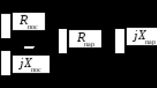
For example, a circuit equivalent circuit is given (Fig. 12). By experiment, the following parameters of the operating mode of this circuit were measured: P- active power of the entire circuit; U- voltage at the circuit terminals; I– input current; I 1 and I 2 – branch currents; phase angle between voltage and current sinusoids (taking into account its sign). It is necessary to determine the parameters of the circuit and build a vector diagram. The following calculations are carried out:
1. Determine the equivalent parameters of the entire circuit (the sign of the total reactance and the total reactance is determined by the sign of the measured angle)
2. Determine the equivalent parameters of each branch
3. Determine the parameters of the elements of the circuit branches
4. Calculate the remaining parameters of the operating mode of the circuit
5. Build vector diagrams of currents, conductivities, powers.
In this circuit, as in a circuit with a serial connection R, L,C- elements, a resonant mode is possible, which is called current resonance. At resonance of currents in a circuit containing L and FROM- elements included in parallel branches, input current sinusoids I and voltage applied to the circuit terminals are in phase, i.e. . The features of this regime have already been considered (Fig. 4, 8, 11). Let us determine the resonant frequency in the circuit (Fig. 1). If for the resonance of currents, then in accordance with (11)
Expression (34) determines the current resonance condition for a particular circuit. If the inductor and the capacitor are connected in parallel branches, then the reactive conductance modules of the branches must be equal.
Substituting these expressions into (34) and solving the equation for , we obtain
Expression (35) shows that the resonant frequency is determined by the value of the four parameters of the circuit L, C, R 1 , R 2. Therefore, the resonant mode can be achieved by varying each of these parameters.
Let us analyze the dependences of the circuit parameters and the parameters of its operation mode on changes C on the example of the diagram in Fig. 12. We consider that the value of the capacitance FROM varies from 0 to , and the circuit is connected to an ideal source of sinusoidal EMF.
Conductivity
When novice hams see an equation for calculating the total resistance of a parallel circuit, they naturally ask,"Where did it come from?" In this article we will try to answer this question.
In view of the fact that electrons, colliding with particles of a conductor, overcome some resistance to movement, it is customary to say that conductors have electrical resistance . Resistance is denoted by the letter "R" and is measured in ohms. However, any conductor can be characterized not only by its resistance, but also by the so-called conductivity - the ability to conduct electricity. Conductivity is the reciprocal of resistance:
The greater the resistance, the lower the conductivity and vice versa. Resistance and conductivity are opposite ways of referring to the same electrical property of materials.If, when comparing the resistances of two components, it turns out that the resistance of the "A" component is half that of the "B" component, then we can alternatively express this relationship by saying that the conductivity of the "A" component is twice that of the "B" component. If the resistance of component "A" is one third of the resistance of component "B", then component "A" can be said to be three times more conductive than component "B", and so on.
Conductivity is denoted by the letter "G", and its unit of measurement was originally "Mo", that is, "Ohm" written backwards. But, despite the relevance of this unit, it was later replaced by "Siemens" (abbreviated as Cm or S).
Now let's go back to our parallel circuit example. Considering it in terms of resistance, having multiple paths (branches) for the flow of electrons reduces the overall resistance of this circuit, since it is easier for electrons to flow along several paths than one with some resistance. If we consider the circuit from the point of view of conductivity, then several paths for the flow of electrons, on the contrary, increase the conductivity of the circuit.
The total resistance of a parallel circuit is less than any of its individual resistances, since multiple parallel branches create fewer impediments to the flow of electrons than each resistor individually:

The total conductivity of a parallel circuit is greater than the conductivity of any of its individual branches, since resistors connected in parallel conduct electric current better than each resistor individually:

It would be more accurate to say that the total conductivity of a parallel circuit is equal to the sum of its individual conductivities:
Knowing that the conductivity is 1/R, we can transform this formula into the following form:

From this formula it can be seen that the total resistance of the parallel circuit will be equal to:

Well, we have found the answer to the question posed at the beginning of the article! You should be aware that conductivity is very rarely used in practice, and therefore this article is purely educational in nature.
Short review:
- Conductivity is the opposite of resistance.
- Conductivity is denoted by the letter "G" and is measured in Mo or Siemens.
- Mathematically, conductivity is the opposite of resistance: G=1/R