How to make an electronic motor with your own hands. Do-it-yourself electric motor: instructions for assembling a homemade mechanism
Who would have thought that the simplest inverter can be made without the use of transistors, microcircuits and complex circuits. I showed you last time. As it turned out, this is not the only way to build an inverter. I'll show you how you can convert electrical energy from 12V DC to 220V AC.
What will be needed?

step up transformer. Naturally, before it worked as a step down, but we will use it the other way around. Such transformers can be found in receivers, electronic clock, old tape recorders.

Assembly of the inverter
In fact, our circuit consists of only three parts connected in series to each other. This is a transformer connected to the circuit with a low-resistance winding (the high-resistance winding is the output of the inverter). Batteries - accumulators or batteries. And a switching element, in the role of which an electric motor will be used, which can be removed from broken children's toys.
Here is the motor itself. Just do not insert it into the circuit - it will not switch. We need to improve it.

To do this, we disassemble the motor.

We remove the back part, before bending the holders.

Anchor needs to be fixed. This consists in disconnecting one winding from the contacts. To do this, we cut off the wires of any one winding.

We assemble the motor.

After such refinement, the motor will not be able to fully spin, since one winding will be turned off. But if you start it by hand, then the motor has enough power to maintain rotation. And the absence of one winding will periodically break the power circuit between the batteries and the transformer, where the motor is connected in series.
We include in the chain.


We connect a multimeter to the output of the transformer. Then turn on the power. It happens that the motor itself starts, but usually not. Then we start the shaft by hand, gently twisting it.

The inverter is working! The multimeter reading jumps from zero to about 250 V. This is normal, since this is a technical inverter to power primitive devices.

Trying to connect Charger. Everything works fine - the phone is charging.

We connect the light bulb - the lamp shines.

Of course, there is no need to talk about the quality of the converted energy, but in difficult life situations, such a craft may well come in handy.
Hello comrades, friends and ill-wishers! A small whale for building (additional assembly) of a collector electric motor. Since this is intended for children (unspecified age), you won’t have to wind the wire, everything will be very light, but interesting for the child. Under the cut - assembly, operation and measurements.
Disclaimer right away - this constructor was sent to me for review by Banggood under item 18. That is. I didn't pay a dime for it and shipping. You will pay real money, please take this into account when forming your own opinion about the product.
So, the second designer waited for the fate of being assembled. Like it just came in a package.
The packaging is a fairly tight box, almost not damaged. It certainly weighs much more. 

The box is abundantly supplied with images of the assembled product, on one of the sides there are large hieroglyphs - we decided with our daughter to consider that there is written a congratulation on the New Year 
It should be noted that much less needlework is expected here than in the previous constructor. But, in fact, the instructions here are short, and absolutely Chinese in dialect, 

and the images on the box are so frankly misinforming! 
(look at how magnets are installed on the print on the box. Nothing embarrassing? Oh, these “full-time photographers” of the manufacturer. In addition, the installation is depicted with the collector up. As will be shown later, in this device “up and down matter”.
Note that on the BangGood website, the images (photos) are correct - the magnets are installed with different poles, the collector with brushes is at the bottom.
Inside our box is: 


Two magnets in the form of a parallelepiped. Quite heavy, but not heavy duty for its size. 
Frame made of plastic. “Brushes” are already fixed and there are bolt clamps for wires 
Rotor with a collector on the axis. 
Two wires with crimped ends for bolts. 
Tin key, for wire clamp 
Well, the aforementioned slurred instructions.
Well, thank God we're in in general terms we know what this is), so after a short lecture, we move on to assembling and consolidating the lesson.
I do not claim to be the best teacher of the year, so I limited myself to a story about what a magnetic field is, why it arises (natural magnets and a magnetic field around a conductor with current) and how magnetic fields can move and / or rotate things.
Most admired was the passage about "aggressive magnets" that push the rotor through magnetic fields. Of course, the simplification is great, but every day he asks to tell again about them.
Assembly does not cause any problems, but it is very embarrassing that the assembled device is shown on the box with magnets installed symmetrically (i.e. N to N) - which contradicts the instructions, the image on the site, and most importantly, the physical meaning. This is sad. Since a child, left to himself, naturally tries to assemble as shown on the box, without waiting for the theses about the poles of magnets. 


Also, on the box and in the instructions, the installation is depicted upwards with a collector, and on the website the picture is vice versa.
In general, confusion.
Eventually self assembly gave this result: 


We are trying to tighten the wire plugs with plastic clamps and are faced with the fact that the black clamp flatly refuses to twist to the state of being pressed. We do not persist, using the complete key, we clamp the wire between the frame and the clamping nut. 


Now we are reworking the installation a little, at the same time explaining what was done wrong)))
Install the magnets following the instructions. We install the rotor with the collector, the axis neatly enters with its sharp ends into the grooves on the upper and lower clamping bolts. We start the collector between the "brushes" so that they are tightly pressed against the collectors with stampings. 
So, everything is assembled, tightened, the axis rotates.
We take the Eneloop battery (2000mAn, the voltage at the time of connection is 1.31V) and ...
Nothing happens. We turn the rotor in different directions. Zero reaction.
Well, let's go along the extensive path - we take lithium ion battery with a voltage of 4.15 volts. The battery is “resembling”, so we do not expect it to give out a large current, which could cause special effects.
I clamp the contacts with my fingers on the battery (yes, I agree, this forms a wrong perception of safety in the child, we will correct it) and I feel that the current is going ... and considerable, judging by how quickly the contacts under the fingers heat up.
They turned the rotor and “yet it spins” ©. 
With bursts of sparks from under the "brushes", our motor is gaining momentum, clearly demonstrating how the current from the battery generates a magnetic field that interacts with the magnetic field of stationary magnets.
The number of turns is quite decent. We shoot with a slowdown of 1/4x in the hope of then counting the revolutions.
The child is delighted and many times asks to repeat “for an encore”, either by scrolling the motor himself, or by pressing the contacts.
Trying to start again on AA battery
Actually, already here you can see that the goal of the designer has been achieved - a little theory, a little practice with your hands and a lot of fun to consolidate the material. Now she asks me every day to "play motor with aggressive magnets."
We remove the assembled product from the child when he has played enough and carry out measurements and improvements.
Unfortunately, it has not yet been possible to achieve autostart of the motor, only with a manual push. Probably, if there were a three-pole anchor here, there would not be such a problem. And this is actually urgent, because a delicate children's finger can suffer during manual start.
The current flowing on an unstarted motor is quite large, more than an ampere (1.21A) from lithium-ion, which means that more than 3 watts goes literally into the air.
After starting, the current drops slightly and stabilizes in the region of 0.8-0.82A
Replacing the battery with a fresh protected Panasonic 3400mAn only leads to the fact that every second time the battery protection cuts off the power. The current does not increase much. (1.1A). But the speed increases (less voltage drop under load than the old Li-Ion)
Slow motion. The upper mount is slightly tightened, the beating is visible.
The number of revolutions does not exceed 40 revolutions per second.
We take grease for bearings and lubricate the conical friction pairs of the rotor axis. We stretch a little. The rotation becomes more even and stable (beats go away) and even the speed seems to increase.
But in any case, the speed is not higher than 40 rpm at a current of 0.95A
Okay, now we take the AA battery.
A couple of unsuccessful attempts and the engine starts on it. But it works weakly, uncertainly and calms down.
The current when the engine is not running is 0.46A
But what if we turn our design over so that the collector is at the bottom - and lo and behold, work from AA is much more confident. Perhaps the point is less friction in this cone pair when working as a support ...
We measure the current, again in the “not running” state and in the “running” state. Again, we shoot a slow-motion video in order to approximately determine the number of revolutions.
Here it is already more or less accurate to say that on the AA element the number of revolutions is in the region of 10-12 revolutions per second.
Nevertheless, our motor strives to stop on the battery, although it eats 0.6A
We also measure the resistance of the winding. Approx 2.5ohm 
The rotor was launched by hand in the manner of a spinning wheel, i.e. it is fairly balanced about the axis.
Here in this photo you can check out the quality of the winding 
Since our "brushes" are just metal stampings, they scratch the collector, God forbid 
weigh-ins
Rotor weight is 24 grams 
The frame weighs 47 grams 
To complete the picture, we weigh the magnets (36 and 37 grams) 
and measure how much in static they can approximately hold metal (by weight). It doesn't really matter, but so be it. (210gr+) 

The resistance of the proposed wiring was 0.2 ohm for the minus one and 0.2 ohm for the plus one. 

In general, I noticed that on the muse, commentators take a special orgastic delight in measuring everything that can be measured, even if it is not important for the product, or its cost does not justify such detail.
I thought about visiting the alma mater laboratory and examining the magnetic fields generated by the magnets and the motor assembly, conducting a study of the materials from which the frame is made (if there are any harmful impurities in the plastic), to clarify whether oxygen-free copper was used for windings. In addition, I was interested in the value luminous flux generated by sparks from brushes crawling along the collector (naturally in boxing). There were more interesting ideas sound pressure measurement. One of my friends seriously argued that I should investigate how swallowing a magnet would affect digestive tract(“You have to,” he shouted, “suddenly one of your readers buys this, but oversights and the child swallows the magnet!”), But on a sound reflection, I refused such a test on myself. Therefore, do not blame me that there is no analysis of the cardiogram of my heart at the moment the engine is started, when I press the contacts with my finger (and what vibrations there should be ... from delight ...).
Summing up, I want to note the following:
1) The instruction is meaningless and defective. There are no details or warnings about applicable power supplies. Moreover, the pictures on the box (incorrect) directly contrast with the pictures in the instructions.
2) The kit is not completely complete, there is no power supply. If people do not have flashlight (lithium ion / polymer reserves), then most likely there will be problems when starting from an AA battery, or the start will not be spectacular (faded). And someone out of a special mind can decide to connect a torn USB wire to the input from a mains power source or even connect 220 volts. Warning labels neither on the box nor in the instructions in a clear English language No
3) Cant with negative clamp.
4) Hoarding at the third pole at anchor. It would be better for a buck more expensive, but with a normal autostart, and not the risk of getting a finger or pinching a finger between the rotor and the magnet
5) In general, inexplicable hoarding on brushes. The surface of the collector wears out very quickly from such operation, brushes cost a penny. You will have to look for something suitable, otherwise the toy will also quickly become disposable.
Now about the pros, and remember that I got it for free, and you will pay something around 500 rubles (!)
1) The toy-constructor is quite large and visual. Perhaps part of the price went into large magnets and copper at anchor)))
2) If you have a 4.2 volt battery, you can start it easily, as well as assemble it. There will be no fail (unless, of course, install the magnets according to the instructions, and not as shown on the box).
3) You can build a whole lecture around it, both in depth for preschoolers and middle-aged schoolchildren (with whom we already go into details regarding windings, the number of poles at the anchor, reducing friction in cone pairs, etc.)
4) in a 4-year-old child, it aroused interest, joy, and a desire to repeat and repeat experiments.
I note that you can build something similar yourself by tearing up some unnecessary small electric motor. So this waste is not an indispensable auxiliary means.
However, if BangGood discounts this model, or you get some points there or whatever, you can make your life easier by ordering and assembling this model, as it is still visual.
I hope that after the review you will be able to form your own opinion whether you need such a training constructor for such money.
Thanks to all.
The product was provided for writing a review by the store. The review is published in accordance with clause 18 of the Site Rules.
I plan to buy +16 Add to favorites Liked the review +37 +61This video is for all novice ham radio experimenters who would like to make a simple mini motor from available radio components. Highly good way to keep your child busy and accustom him to technical knowledge. Be sure that your child will show his knowledge in physics lessons at school.
Let's assemble a simple electric motor
Let's repeat the old school experiment. What you need to prepare for homemade:
Battery 2a. Enamelled wire with a cross section of 0.5 mm. Magnet. Two pins, stationery tape, plasticine. Tool. First, let's make a coil. We wind it from enameled wire. We make 6-7 turns around the battery. We fix the ends of the wire with knots. Now you need to properly clean the varnish on the coil. it important point- the performance of the engine depends on the correct execution. One end is completely cleared of insulation. The other is on one side. This side must match bottom coils.
We fix the pins on the battery with tape. We check the contacts with a tester. Install the magnet. In this case, it's weak. Therefore, you have to lift it closer to the coil. We fix the structure on the table with plasticine. The coil must be installed correctly. When it is set, the bare ends should touch the pins.
The principle of operation of the simplest micro motor
A magnetic field is generated in the coil. It turns out an electromagnet. poles permanent magnet and coils should be the same. That is, they must repel. The repulsive force turns the coil. One of the ends loses contact and the magnetic field disappears. By inertia, the coil turns. The contact reappears and the cycle repeats.
If the magnets are attracted, the engine will not spin. Therefore, one of the magnets will need to be turned over.
We start the motor. We can give a little practicality to this product. Attach a hypnotic coil to one end of the coil. Fascinating! You can make a famous thaumatrope with a bird in a cage.
Channel “OlO”
A more advanced homemade engine for studying electromagnetic phenomena
Video “99%DIY”. 
 We need a wine cork. First of all, we make a hole in the center. On both sides we cut out small planes. Insert the knitting needle into the hole. Fix with superglue. We wind electrical tape on the knitting needle. We install two pieces of copper wire inside the cork.
You will need insulated thin copper wire to create a mini motor. The master used a length of 5 m and a diameter of 0.4 mm. We wind in the 1st direction on the motor rotor. We remove the insulation from the terminals of the winding. We connect the wires to the contacts. We fix the winding with superglue. We give contacts the following form. The motor rotor is ready.


Now let's make the body. This will require wooden base and two small bars in which we make holes. Bars and glue on the base. Install the motor rotor.
From two pieces of copper wire we will make brushes for a mini motor.


Why do you need two magnets. Glue on small wooden blocks. We glue the blanks on the base, leaving a minimum gap between the magnets and the winding. The electric motor is ready. Now let's move on to testing.

As you can see in the filmed video, this miniature engine has a lot of backlash and does not have much power. But this is not important for such a homemade product, it is designed to study electromagnetic phenomena that often take place at school superficially, without the use of special experiments. It is impossible to study the subject without visual and practical actions, especially when it comes to electricity. Here the imagination is a weak helper.
However, as you may have also noticed, you can attach some kind of drive to the motor shaft. For example, the fan will work. When you have mastered this video tutorial, you can proceed to a more advanced motor. Use bearings to reduce friction. Then the efficiency of a do-it-yourself device can compete with industrial products of this kind.
Consider some aspects of design. We will not promise the manufacture of a perpetual motion machine, according to the type of creation attributed to Tesla, but the story is expected to be interesting. We will not disturb readers with paper clips and batteries, we propose to talk about how to adapt a ready-made motor for your own purposes. It is known that there are a lot of designs, all are used, but modern literature leaves the basic foundations behind the stern. The authors studied the textbook of the last century, learning how to make an electric motor with their own hands. Now we offer to plunge into the knowledge that makes up the basis of a specialist.
Why are collector motors often used in everyday life?
If we take the phase at 220V, the principle of operation of the electric motor on the collector makes it possible to make devices 2-3 times less massive than when using an asynchronous design. This is important in the manufacture of appliances: hand blenders, mixers, meat grinders. Among other things, it is difficult to accelerate an asynchronous motor above 3000 rpm; there is no specified limitation for collector motors. What makes the devices the only ones suitable for the implementation of designs of centrifugal juicers, not to mention vacuum cleaners, where the speed is often not lower.
There is no question of how to make an electric motor speed controller. The problem was solved a long time ago by cutting off part of the supply voltage sinusoid cycle. This is possible, because the collector motor does not care whether it is powered by a variable or direct current. In the first case, the characteristics fall, but the phenomenon is tolerated because of the obvious benefits. The electric motor of the collector type works and in washing machine, and in the dishwasher. Although the speeds are very different.
Easy to do and reverse. To do this, the polarity of the voltage on one winding is changed (if both are affected, the direction of rotation will remain the same). Another task is how to make an engine with a similar number of components. It is unlikely that it will be possible to make a collector on your own, but it is quite possible to rewind and pick up a stator. Note that the rotation speed depends on the number of rotor sections (similar to the amplitude of the supply voltage). And on the stator there are only a couple of poles.
Finally, when using this design, it is possible to create a universal device. The motor runs easily on both AC and DC. It’s just that a tap is made on the winding, when turned on from the rectified voltage, the turns are fully used, and with a sinusoidal only a part. This allows you to keep the nominal parameters. Making a primitive collector-type electric motor does not look like an easy task, but it will be possible to fully adapt the parameters to your own needs.
Features of the collector motors
In a commutator motor, there are not too many poles on the stator. To be more precise, there are only two - northern and southern. The magnetic field, as opposed to asynchronous motors, does not rotate here. Instead, the position of the poles on the rotor changes. This state of affairs is ensured by the fact that the brushes gradually move along the sections of the copper drum. The special winding of the coils ensures proper distribution. The poles seem to slide around the circle of the rotor, pushing it in the right direction.
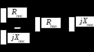
To ensure the reverse mode, it is enough to change the polarity of the power supply of any winding. The rotor in this case is called the armature, and the stator is called the exciter. It is permissible to include these circuits in parallel to each other or in series. And then the characteristics of the device will begin to change significantly. This is described by mechanical characteristics, take a look at the accompanying drawing to show what is claimed. Here, graphs are conditionally shown for two cases:

- With parallel supply of the exciter (stator) and the armature (rotor) of the collector motor with direct current, its mechanical characteristic almost horizontal. This means that when the load on the shaft changes, the nominal shaft speed is maintained. This applies to machine tools where the speed change is not in the best way affects quality. As a result, the part rotates briskly when touched by a cutter, as at the start. If the obstructing moment increases too much, stalling occurs. The engine stops. Summary: if you want to use the engine from a vacuum cleaner to create a metalworking (lathe) machine, it is proposed to connect the windings in parallel, because in household appliances a different type of inclusion dominates. And the situation is understandable. When the windings are supplied in parallel with alternating current, too much inductive resistance is formed. The specified methodology should be used with caution.
- When the rotor and stator are fed in series, a lovely property appears in the collector motor - a large torque at the start. This quality is actively used for breaking trams, trolleybuses and, probably, electric trains. The main thing is that when the load increases, the speed does not break. If you start in this mode the collector engine for Idling, the speed of rotation of the shaft will increase immensely. If the power is low - tens of W - you should not worry: the friction force of bearings and brushes, the increase in induction currents and the phenomenon of remagnetization of the core together will slow down growth at a specific value. In the case of industrial units or the aforementioned vacuum cleaner, when its engine is removed from the housing, the speed increase is like an avalanche. The centrifugal force is so great that the loads can break the anchor. Be careful when starting collector motors with series excitation.
Collector motors with parallel connection of the stator and rotor windings are perfectly adjustable. By introducing a rheostat into the exciter circuit, it is possible to significantly increase the speed. And if such an anchor is attached to the branch, the rotation, on the contrary, will slow down. This is widely used in technology to achieve the desired characteristics.
The design of the collector motor and its connection with losses
When designing commutator motors, information regarding losses is taken into account. There are three types:

Usually, when supplying a collector motor with alternating current, the windings are connected in series. Otherwise, there is too much inductive reactance.
To the above, we add that when the collector motor is powered by alternating current, the inductive resistance of the windings comes into play. Therefore, at the same operating voltage, the speed will decrease. The stator poles and housing are protected from magnetic losses. It is easy to verify the need for this by simple experience: feed a low-power collector motor from a battery. His body will remain cold. But if now apply alternating current with the previous effective value (according to the testimony of the tester), the picture will change. Now the housing of the collector motor will start to warm up.

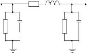
Therefore, they even try to assemble the casing from sheets of electrical steel, riveting or gluing with the help of BF-2 and analogues. Finally, let's supplement what has been said with the statement: the sheets are typed along the cross section. Often the stator is assembled according to the sketch shown in the figure. In this case, the coil is wound separately according to the template, then insulated and put back on, simplifying assembly. As for the techniques, it is easier to cut steel on a plasma machine, and not think about the cost of the event.
It is easier to find (in a landfill, in a garage) a ready-made form for assembly. Then wind coils of copper wire with varnish insulation under it. Obviously the diameter is larger. First, the finished coil is pulled onto the first protrusion of the core, then onto the second. Press the wire so that a small air gap remains at the ends. It is believed that this is not critical. To hold on, sharp corners are cut off at the two extreme plates, the remaining middle is bent outward, squeezing the ends of the coil. This will help to assemble the engine to factory standards.
Often (especially in blenders) there is an open stator core. This does not distort the shape of the magnetic field. Since there is only one pole, there is no need to expect special power. The shape of the core resembles the letter P; a rotor rotates between the legs of the letter in a magnetic field. Under the device, circular slots are made in the right places. It is not difficult to assemble such a stator yourself from an old transformer. It's easier than making an electric motor from scratch.
The core at the winding point is insulated with a steel sleeve, on the sides - with dielectric flanges cut from any suitable plastic.
Almost everything in our life depends on electricity, but there are certain technologies that allow us to get rid of local wired energy. We propose to consider how to make a magnetic motor with your own hands, its principle of operation, scheme and device.
Types and principles of operation
There is a concept of perpetual motion machines of the first order and the second. First order are devices that produce energy by themselves, from the air, second type- these are engines that need to receive energy, it can be wind, sunlight, water, etc., and they already convert it into electricity. According to the first law of thermodynamics, both of these theories are impossible, but many scientists disagree with this statement, and they began the development of second-order perpetual motion machines powered by magnetic field energy.
Photo - Dudyshev's magnetic motorA huge number of scientists have worked on the development of the "perpetual motion machine" at all times, the greatest contribution to the development of the theory of the magnetic motor was made by Nikola Tesla, Nikolai Lazarev, Vasily Shkondin, the variants of Lorentz, Howard Johnson, Minato and Perendev are also well known.
 Photo - Lorenz magnetic motor
 Each of them has its own technology, but they are all based on the magnetic field that is formed around the source. It is worth noting that "perpetual" motion machines do not exist in principle, because magnets lose their abilities after about 300-400 years.
The simplest is homemade a Lorenz anti-gravity magnetic thruster. It works at the expense of two differently charged disks that are connected to a power source. The discs are half placed in a hemispherical magnetic screen, the field of which they begin to gently rotate. Such a superconductor very easily pushes the magnetic field out of itself.
Protozoa Tesla asynchronous electromagnetic motor based on the principle of a rotating magnetic field, and is able to produce electricity from its energy. An insulated metal plate is placed as high as possible above ground level. Another metal plate is placed in the ground. The wire is passed through a metal plate on one side of the capacitor and the next conductor goes from the base of the plate to the other side of the capacitor. The opposite pole of the capacitor, being connected to ground, is used as a reservoir for storing negative energy charges.
 Photo - Tesla magnetic motor
 Rotary ring Lazarev so far it is considered the only working VD2, in addition, it is easy to reproduce, you can assemble it yourself at home, having improvised tools in use. The photo shows a diagram of a simple Lazarev ring engine:
 Photo - Koltsar Lazarev
 The diagram shows that the container is divided into two parts by a special porous partition; Lazarev himself used a ceramic disk for this. A tube is installed in this disk, and the container is filled with liquid. For the experiment, you can even pour plain water, but it is desirable to use a volatile solution, for example, gasoline.
The work is carried out as follows: with the help of a partition, the solution enters the lower part of the tank, and due to pressure it moves up through the tube. So far, this is only perpetual motion, not dependent on external factors. In order to build a perpetual motion machine, you need to place a wheel under the dripping liquid. On the basis of this technology, the simplest self-rotating magnetic electric motor of constant motion was created, a patent was registered for one Russian company. It is necessary to install a wheel with blades under the dropper, and place magnets directly on them. Due to the formed magnetic field, the wheel will start to rotate faster, water will be pumped faster and a permanent magnetic field will be formed.
Shkondin linear motor made a kind of revolution in progress. This device is very simple in design, but at the same time incredibly powerful and productive. Its engine is called a wheel within a wheel, and it is mainly used in the modern transportation industry. According to reviews, a motorcycle with a Shkondin engine can travel 100 kilometers on a couple of liters of gasoline. The magnetic system works for full repulsion. In the wheel-in-wheel system, there are paired coils, inside of which one more coils are connected in series, they form a double pair, which has different magnetic fields, due to which they move in different directions and a control valve. An autonomous motor can be installed on a car, a fuel-free motorcycle with a magnetic motor will not surprise anyone, devices with such a coil are often used for a bicycle or a wheelchair. You can buy a finished device on the Internet for 15,000 rubles (made in China), the V-Gate starter is especially popular.
 Photo - Shkondin Engine
 Alternate Perendeve Engine- This is a device that works solely thanks to magnets. Two circles are used - static and dynamic, on each of them in equal sequence, magnets are located. Due to the self-repelling free force, the inner circle rotates indefinitely. This system received wide application in providing independent energy in the household and production.
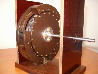 Photo - Engine Perendeva
 All of the above inventions are under development, modern scientists continue to improve and search for them. perfect option to develop a perpetual motion machine of the second order.
In addition to these devices, the Alekseenko vortex engine, Bauman, Dudyshev and Stirling devices are also popular with modern researchers.
How to assemble the engine yourself
Homemade products are in great demand on any electrician forum, so let's look at how you can assemble a magnetic motor-generator at home. The fixture that we propose to construct consists of 3 interconnected shafts, they are fastened in such a way that the shaft in the center is turned directly to the two side ones. Attached to the middle of the central shaft is a disk of lucite, four inches in diameter, and half an inch thick. The outer shafts are also equipped with two inch discs. There are small magnets on them, eight pieces on a large disk and four on small ones.
 Photo - Suspended magnetic motor
 The axis on which the individual magnets are located is in a plane parallel to the shafts. They are installed in such a way that the ends pass near the wheels with a flash of a minute. If these wheels are moved by hand, then the ends of the magnetic axis will be synchronized. To speed up, it is recommended to install an aluminum bar in the base of the system so that its end slightly touches the magnetic parts. After such manipulations, the structure should begin to rotate at a speed of half a turn in one second.
The drives are installed in a special way, with the help of which the shafts rotate similarly to each other. Naturally, if you act on the system with a third-party object, for example, with a finger, then it will stop. This perpetual motion machine was invented by Bauman, but he failed to obtain a patent, because. at that time, the device was classified as non-proprietary VD.
For development modern version Chernyaev and Emelyanchikov did a lot of such an engine.
 Photo - The principle of operation of the magnet
 What are the advantages and disadvantages of actually working magnetic motors
Advantages:
- Complete autonomy, fuel economy, the ability to organize the engine from improvised means in any desired place;
- A powerful device on neodymium magnets is capable of providing energy to a living space up to 10 W and above;
- The gravitational engine is able to work until it is completely worn out, and even at the last steel, work is given out maximum amount energy.
Flaws:
- The magnetic field can negatively affect human health, especially the space (jet) engine is subject to this factor;
- Despite the positive results of the experiments, most models are not able to work under normal conditions;
- Even after acquiring a ready-made motor, it can be very difficult to connect it;
- If you decide to buy a magnetic impulse or piston engine, then be prepared for the fact that its price will be greatly inflated.
The operation of a magnetic motor is pure truth and it is real, the main thing is to correctly calculate the power of the magnets.