Technological tests. Mechanical properties of metal and technological testing of pipes
5. Technological tests of metals and alloys
The ability of metals and alloys to undergo various types of technological processing (processing by pressure, cutting, welding) depends on their technological properties. To determine the technological properties, tests are carried out on technological samples that are most often used in production conditions. Technological samples include tests for bending, upsetting, flattening, beading, pipe bending and many others. Many technological samples and test methods are standardized.
Based on the results of technological tests, the possibility of manufacturing a high-quality product from a given material is determined under conditions corresponding to the technological process adopted in this production.
Bending test (GOST 14019 - 80) is used to determine the ability of materials to withstand specified bending deformations without destruction. Sample / (Fig. 6, a) with the help of a mandrel 2 is bent under the action of the force of the press between rollers 3 to a given angle a. The ability of a material to withstand bending deformation is characterized by a given bending angle a. When the sample is bent through 180°, the material is able to withstand the ultimate bending strain. Samples that have passed the test must not have cracks, tears, delaminations.
The bending test is subjected to sheets up to 30 mm thick, long products - bars, channels, corners.
Rice. 6. Technological tests:
a - for bending, b - for draft, c - for flattening pipes, d - for beading pipes, e - for bending pipes; 1 - sample, 2 - mandrel, 3 - rollers,
Sample before upsetting, 5 - sample after upsetting, 6 - pipe
The upset test (GOST 8817--82) is used to determine the ability of a metal to withstand a given plastic deformation. Sample 4 is deposited in a hot or cold state using a press or hammer to a certain height h (Fig. 6.6). The slump test is carried out on round or square samples with a diameter or side of a square in a cold state from 3 to 30 mm, in a hot state - from 5 to 150 mm. The height of steel samples should be equal to two diameters, and samples of non-ferrous alloys - at least 1.5 diameters. The sample is considered to have passed the test if no cracks, tears or breaks appear on it.
Pipe flattening test (GOST 8695 - 75) is used to determine the ability of pipes to flatten to a certain height H (Fig. 6, c) without cracks and tears. The end of the pipe 6 or its segment 20...50 mm long is flattened between two parallel planes. If the pipe is welded, then the seam on the pipe should be located along the horizontal axis, as shown in the figure. Flattening of pipes is carried out smoothly at a speed of no more than 25 mm/min. The sample is considered to have passed the test if no cracks or tears appear on it.
The pipe beading test (GOST 8693--80) is used to determine the ability of pipes to be beaded at an angle of 90 °. The end of the pipe 6 (Fig. 6, d) is beaded with the help of a mandrel 2 with a force P of the press until a flange of a given diameter D is obtained. The working surface of the mandrel must be cleanly machined and have high hardness (HRC not less than 50). The radius of curvature of the mandrel, which forms the bead, must be equal to twice the thickness of the pipe wall (R=2s). Beading is considered to be of high quality if no tears or cracks are found on the flange.
Pipe bend test (GOST 3728--78) is used to determine the ability of pipes to bend without cracks and tears at an angle of 90 °. Before testing, pipe 6 (Fig. 6, (3)) is filled with clean, dry river sand or other filler. The test consists in smooth bending of the sample in any way that allows bending the sample so that its outer diameter D in no place becomes less than 85% from the initial For testing pipes with an outer diameter of up to 60 mm, their segments are used, with a diameter of 60 mm or more - longitudinal tapes 10 mm wide cut from pipes.
A weldability test is performed to determine the strength of a welded butt joint. The welded sample is subjected to bending (see Fig. 6, a) at a given angle a or tested in tension. The strengths of the welded and unwelded samples of the test metal are then compared.
Types of cast iron. Properties of non-ferrous metals
In technology, all non-ferrous metals are classified as non-ferrous. Based on them, a large number of alloys have been created with a wide range of properties that meet the requirements for aviation materials. These include: significant mechanical strength...
As a result of the use of magnetic-pulse processing, it seems possible to stamp sheet and tubular blanks up to 5 mm thick. The dimensions of the workpieces (diameter, cultivated area) are determined by the energy reserve of the installation ...
High-performance metal forming methods
Superplasticity is defined as the ability of polycrystalline (ultrafine-grained) materials to uniformly plastically deform to very large degrees (up to Ek > 200%) at relatively high temperatures and low stresses (2.....
High-performance metal forming methods
Superplasticity is most often used in forging technology...
Production of parts by plastic deformation methods
Rolling of metals is a method of processing metals and metal alloys by pressure, which consists in compressing them between rotating rolls of rolling mills. The rolls are mostly in the form of cylinders...
Test station for turboprop engines TV3-117 VMA-SBM1 serial production
Type tests are carried out in order to: - verify the design and technological changes made to improve the serial engine; - checking repair technology...
Crystallization of metals and alloys
Crystallization - the transition of a metal (alloy) from a liquid state to a solid state - occurs under conditions ...
Casting properties of alloys. Rolling mill. Physical basis of welding
Welding is the process of obtaining an integral connection of individual parts of solid materials due to interatomic cohesive forces, both with and without heating ...
Modernization of the sclerometric complex for measuring hardness
The essence of the method lies in the fact that a striker of a certain mass with a diamond tip falls freely and vertically from a certain height onto the test surface [SamGTU.200501.059.009.06]...
Basic information about materials
Metals are simple substances that have free electrons not associated with certain atoms, which are able to move throughout the volume of the body. This feature of the state of a metallic substance determines the properties of metals ...
The structure and properties of alloys
Material forming technology
Cold stamping is understood as the stamping of metals and alloys without preheating the workpiece, i.e. at room temperature...
Production technology and consumer properties of hard tungsten-free alloys
Quality control of hard sintered tungsten-free alloys is carried out in accordance with GOST 20019-74 “Hard sintered alloys. Strength determination method”; GOST 20017-74 "Hard sintered alloys...
Welding technology
Weldability of metals and alloys is evaluated by their weldability. Weldability is the property or combination of properties of metals to form, with the established welding technology, a joint that meets the requirements ...
Test
according to metal processing technology
Subject: Sheet Metal Machining
1. Determination of suitability of sheet material for deep drawing by Eriksen test
2. Flanging of round holes
3. Cutting-punching with an elastic tool
4. Determination of the parameters of superplasticity of metals
Literature
1. Determination of suitability of sheet material for deep drawing by Eriksen test
The suitability of a metal for drawing can be established by plasticity indicators determined by the results of testing specimens for linear tension: P, anisotropy coefficient R b.
High drawability is shown by metals having
y t / y v \u003d 0.65 - 0.75, P > 0,2, R b? 1.0.
Tensile tests and the determination of the above metal ductility indicators require special equipment, highly qualified personnel, and a significant investment of time. Therefore, such tests are carried out in laboratory conditions. In production, simpler and less time-consuming technological tests are carried out. One of these tests is the test for drawing a spherical hole according to GOST 10510-80 (Eriksen method) on the MLT-10G device.
Eriksen testing of sheet material refers to technological tests, which are understood as the identification of the ability of sheet metal to undergo plastic deformations similar to those that it experiences during technological processing.
Three main types of tests are used to determine the suitability of a material for sheet metal forming operations:
v tests on the depth of extrusion of a spherical hole;
v cap drawing depth tests;
v hole stretch.
The MLT-10G device allows you to carry out all three of the above types of tests.
The Eriksen method consists in drawing a spherical hole in a sample clamped along the contour using a punch 3 with a spherical working surface (Fig. 1.1).
The sample is clamped between the matrix 1 and clamping ring 2 . The test termination criterion is the moment of crack formation on the sample surface. Depth is a measure of the ability of a metal to draw. h elongated hole. Depending on the depth of the elongated hole, the metal is classified into one or another category of drawing (Table 1.1).
Figure 1.1 - Scheme of drawing a spherical hole: 1 - matrix; 2 - clamping ring, 3 - punch
Table 1.1 - Standards for testing materials according to the Eriksen method
In accordance with GOST 10510--80 clamping force Q sample to matrix should be 10 - 11 kN.
In addition to the main indicator of the test - the depth of the drawing of the spherical hole - the quality of the metal can be judged by the nature of the destruction and the state of the surface of the elongated hole. Sample rupture along a circular arc (Fig. 1.2, A) indicates the isotropy of the metal. Rupture in a straight line (Fig. 1.2, b) indicates the banding of the metal microstructure. The smooth surface of the hole indicates a fine-grained structure, and a rough ("orange peel") - a sign of a coarse-grained metal structure.
Figure 1.2 - Types of destruction of blanks during drawing (forming) of a spherical hole
material support
v testing machine MTL-10G (Fig. 1.3);
v a set of equipment for drawing (forming) a spherical segment: a punch with a diameter of 20 mm, a matrix, a clamping ring, a caliper, a micrometer;
v samples from sheet carbon or structural steel with a thickness of 0.8 - 2.0 mm in the form of cards measuring (70-100) x (70-100) mm or circles with a diameter of 70-100 mm.
Figure 1.3 - Scheme of the MTL-10G testing machine: 1 - steering wheel; 2 - washer with markings; 3 - sleeve with clamping ring; 4 - spherical punch; 5 - exhaust point; 6 - mirror; 7 - spring-loaded stopper; 8 - screw.
Machine MLT-10G works as follows. By turning the handwheel 1, the sleeve 3 is moved to the right, connected to the body by a threaded connection, as well as the screw 8, locked in the sleeve 3 by a spring-loaded stopper 7. In this case, the workpiece is hard pressed between the clamping ring of the sleeve 3 and the exhaust point 5.
Further, by compressing the spring, the stopper 7 is released from the blind groove in the screw 8. With further rotation of the handwheel 1, the screw 8 moves along the thread in the hole in the sleeve 3 to the right with the sleeve 3 stationary. point 5. The formation of a crack in the molded workpiece is fixed visually using a mirror 6.
2. Flanging of round holes
metal hole punching superplasticity
Hole flanging is widely used in stamping production, replacing drawing operations with subsequent cutting of the bottom. Hole flanging is especially effective in the manufacture of parts with a large flange, when drawing is difficult and requires several transitions. At present, holes with a diameter of 3 h 1000 mm and a material thickness of 0.3 h 30 mm are obtained by flanging.
Flanging is understood as the operation of cold sheet stamping, as a result of which a bead is formed along the inner (inner flanging) or outer (outer flanging) contour of the workpiece. Basically, internal flanging of round holes is performed. The formation of the bead in this case is carried out by pressing a part of the workpiece into the hole of the matrix with a punched hole previously or simultaneously with the flanging. The scheme of flanging round holes is shown in Figure 2.1. A variation of flanging is flanging with wall thinning.
Figure 2.1 - Schemes for flanging round holes: a) with a spherical punch; b) cylindrical punch
Flanging of round holes is performed spherical (Figure 2.1 A) or a cylindrical punch (Figure 2.1 b). In the latter case, the working end of the punch is made in the form of a retainer (catcher), which ensures the centering of the workpiece along the hole, with a conical transition to the working part of the diameter d P.
The deformation of the metal during flanging is characterized by the following changes: elongation in the tangential direction and a decrease in the thickness of the material, as evidenced by the radial-annular mesh applied to the workpiece (Figure 2.2). The distances between the concentric circles remain unchanged.
Figure 2.2 - Workpiece before and after flanging
The degree of deformation during the flanging of holes is determined by the ratio between the diameter of the hole in the workpiece d and side diameter D or the so-called flanging factor:
TO = d/D,
Where D determined by the midline (see figure 2.2).
If the flanging ratio exceeds the limit value TO before, then cracks form on the walls of the board.
The limiting flanging factor for a given material can be analytically calculated using the formula:
where h is the coefficient determined by the flanging conditions;
d is elongation determined from tensile tests.
The value of the limiting flanging coefficient depends on the following factors:
1) the nature of processing and the condition of the edges of the holes (drilling or punching, the presence or absence of burrs);
2) relative workpiece thickness s/D;
3) the type of material and its mechanical properties;
4) the shape of the working part of the punch.
There is a direct dependence of the maximum allowable flanging coefficient on the relative thickness of the workpiece, i.e. with a decrease d/s the value of the maximum allowable flanging coefficient TO before decreases and the degree of deformation increases. In addition, the value TO pre depends on the method of obtaining a flanged hole, as shown in table 2.1 for mild steel. Table 2.2 lists the flanging factor limits for non-ferrous materials.
The allowable value of bead wall thinning during flanging due to hole edge defects (burrs, hardening, etc.) is significantly lower than the value of transverse narrowing during a tensile test. The smallest thickness at the edge of the board is:
Table 2.1 - Estimated values TO pre for mild steel
|
Punch type |
Hole making method |
Values TO before depending on d/s |
|||||||||||
|
spherical |
|||||||||||||
|
hole in the die |
|||||||||||||
|
cylindrical |
drilling with deburring |
||||||||||||
|
hole in the die |
The calculation of the technological parameters of the flanging of round holes is carried out as follows. The initial parameters are the inner diameter D ext flanged hole and side height H specified by the detail drawing. According to the specified parameters, the required diameter is calculated d technological hole.
Table 2.2 - Values TO pre for non-ferrous metals and alloys
For a relatively high side diameter calculation d are performed based on the equality of the volumes of the workpiece before and after flanging:
Where D 1 = d n + 2( r m+ s).
In this formula, the geometric parameters are determined according to Figure 2.1.
For a low bead, the calculation can be performed from the condition of conventional bending in a radial section:
d = D + 0,86r m - 2 H - 0,57s.
Then check the possibility of flanging in one transition. To do this, compare the flanging factor (see page 14) with the limit value TO before: TO > TO prev.
The flanging force of round holes with a cylindrical punch can be approximately determined by the formula
where s T is the yield strength of the material.
The nature of the change in force during flanging is shown in Figure 2.3, depending on the shape of the outline of the working part of the punch.
Figure 2.3 - Force diagrams and transitions of flanging of round holes with various punch shapes: A) curvilinear; b) spherical; V) cylindrical
3. Cutting-punching with an elastic tool
The use of traditional methods of sheet stamping is associated with the manufacture of expensive stamping equipment and is effective only in large-scale and mass production. In small-scale and pilot production, cold sheet stamping in the case of using conventional die designs is economically unprofitable, that is, the cost of stamping equipment is not paid off.
One of the cost-effective stamping methods in small-scale and pilot production is stamping with an elastic tool, when one of the working tools is made of rubber or polyurethane. This significantly simplifies the design of the tool and reduces the cost of its manufacture, there is no need to manufacture and fit a second working tool, and the time for preparing production is reduced.
Stamping with an elastic tool is used both for separating operations - cutting-punching, and for shape-changing operations - bending, drawing and molding.
Rubbers and polyurethanes are used as elastic media for stamping. Rubbers are less wear-resistant and operate at relatively low pressures, usually not exceeding 20 h 30 MPa.
Recently, polyurethane has been increasingly used instead of rubber. Polyurethanes are more wear-resistant and withstand pressures of the order of 1000 MPa (in closed volumes). The strength of polyurethane is 6 hours 8 times higher than that of rubber, and reaches 600 MPa. Most often, polyurethanes of the SKU-6L, SKU-7L, SKU-PFL brands are used. The latter brand is usually used for separating operations.
Elastic media are especially effectively used when performing separating operations. Using polyurethane, you can cut parts from aluminum alloys up to 3 mm thick; from steel (alloyed and carbon), brass and bronze up to 2 mm thick.
A typical universal equipment for punching and punching is shown in Figure 3.1. In one stroke of the press, the part is punched along the contour and holes and grooves are punched in accordance with the configuration of the cutout template. The container in which the elastic tool is located is usually made of steel 40X with a hardness after normalization HRC 28h 32.
Cut-out templates of a simple configuration and a thickness of more than 2 h 3 mm are made of carbon steel grades U 8, U 8A, U 10, U 10A. Thinner and more complex contour templates are made from alloyed steel grades X 12, X 12M, X 12F 1. The hardness of the template after hardening is HRC 56 h 60, work surface roughness after sanding Ra 0.25 h 1.00.
When cutting parts, the height of the cutout template is of great importance, on which the amount of material waste and the quality of the part depend. Optimal template height H(in mm), which provides high-quality cutting of a workpiece from a plastic material, can be determined by the formula
where d p - relative uniform elongation of the material;
s- material thickness, mm.
Figure 3.1 - Stamp for cutting-punching with elastic media: 1 - container; 2 - washer; 3 - elastic tool; 4 - blank; 5 - cutout template; 6 - stamping plate
Elastic block height H e (mm) is selected from the condition
H e 3 H + 10, (3.2)
Where H is taken in millimeters.
Required material allowance L(mm) when punching parts with a simple contour is determined by the formula
Where f- coefficient of friction between the workpiece and the die plate.
When punching parts with a curved contour, the allowance L(mm) is determined by:
Where R where is the radius of curvature of the contour of the part (the plus sign is taken for a convex contour, the minus sign for a concave one).
The pressure required to cut a part along a contour depends on the mechanical properties of the material, its thickness and the height of the cutout template. For a convex (plus sign) or concave (minus sign) curved section, the cutting pressure q is determined by the formula
and for a straight section according to the formula
q = s s to / H. (3.6)
For punching small holes d pressure is:
q = 3s s to / d, (3.7)
and for cutting small grooves with dimensions A b
When simultaneously punching a part along the contour and punching holes and grooves, the required pressure should be determined by the maximum value q max , which, as a rule, corresponds to the punching of holes and grooves with the smallest area.
Press force R, necessary for the implementation of the separating operation, is determined taking into account the coefficient of losses due to friction and compression of the elastic tool according to the formula
R = 1,2Fq max , (3.9)
Where F- the area of the working surface of the elastic tool.
4. Determination of the parameters of superplasticity of metals
Superplasticity is the state of a deformable material with a special structure that occurs at a high homological temperature and is characterized by abnormally high ultimate degrees of deformation without breaking the continuity of the material under the influence of stresses, the magnitude of which is very low and strongly depends on the strain rate and structure of the material.
Thus, three conditions are necessary for transferring materials to a superplastic state:
1. A special structure is an ultrafine equiaxed grain with a size of no more than 25 microns. Such a structure provides a different deformation mechanism at the superplasticity temperature - intergranular slip.
2. Optimum temperature T = 0.7 ... 0.85 Tm. (Tm is the melting point of the metal). At T< 0,7 Тпл диффузионная подвижность зерен невелика для реализации межзеренного скольжения. При Т >0.85 Tm, intensive grain growth occurs, which inhibits the processes of intergranular slip, which leads to the disappearance of the effect of superplasticity in the metal.
3. Deformation rate d: low enough for complete passage of diffusion processes and high enough to prevent grain growth at high temperatures; for materials with an ultrafine-grained structure of 1-10 µm d = 10 -5 ... 10 -3 s -1 , for materials with submicron grain 0.1-1 µm d = 10 -0 ... 10 -3 s -1 , for materials with nanocrystalline structure 100-10 nm d = 10 -1 ... 10 1 s -1 , for amorphous materials 10 3 ... 10 5 s -1 .
Signs of the state of superplasticity:
1. Increased sensitivity of the flow stress S to a change in the strain rate d, i.e. increased tendency to speed hardening. The rate sensitivity of the flow stress to the strain rate is determined by the coefficient
m = dlnS /dln th > 0.3.
2. Large resource of deformation ability (quasi-uniform deformation by hundreds and thousands of percent according to the principle of a running neck).
3. The flow stress in the SP state is several times less than the yield strength of materials during plastic deformation.
The relationship between the force and strain-speed parameters of metals and alloys treated by pressure, in general terms, is as follows:
S = Ce n th m , (4.1)
where e and d are the logarithmic degree and rate of deformation;
C is a coefficient depending on the temperature and structure of the metal.
For superplastic materials, there is practically no strain hardening, that is, n = 0, e n = 1, and equation (1) takes the form:
S = Кй m , (4.2)
while K? WITH.
All methods for determining the parameter m are based on a comparison of the flow stress S at a minimum of two strain rates d.
From formula (2), the indicator m can be determined by the equation:
m = dlnS /dln th (4.3)
The procedure for determining m is that the sample is stretched or compressed to the maximum force, and then, in the area of steady flow (at a constant or decreasing load), the strain rate is sharply increased from v 1 to v 2 (Fig. 4.1.).
Figure 4.1 - Scheme of the force-time curve for determining the exponent m by the method of stepwise change in the speed of the traverse
Upon reaching a new maximum effort and the beginning of a steady flow, the speed of the traverse is changed again, decreasing or increasing it.
The desire to more fully meet the requirements of the same pre-strain and structure invariance led to the development of different calculation methods using different points on the curve in Fig. 4.1. Let's consider some of them.
1. According to the Backofen method:
where P A is the maximum force at v 2 , and P B is the force obtained by extrapolating the section CD at speed v 1 to a deformation equal to the deformation at a point at speed v 2 . The value of m obtained by equation (4.4) is attributed to some average strain rate calculated from v 1 and v 2 under the condition of uniform deformation.
Bacofen's method is inaccurate due to extrapolation errors.
2. Morrison's method does not require extrapolation, since m is determined by the equation:
where S A and S C are the true stresses at the points of maximum effort for the compared speeds;
S A \u003d 4P A / p (D 2 A), D A \u003d DovNo / (H o - D A);
S C \u003d 4P C / p (D 2 C), D C \u003d DovNo / (H o - D C),
D o and H o - the initial dimensions of the samples;
D A, D C - absolute deformation of the samples at points A and C.
d A and d C - true strain rates,
th A \u003d V A / (N o - D A), s -1;
th C \u003d V C / (N o - D C), s -1,
where V A and V C are the strain rates at points A and C, mm/s.
However, different deformations correspond to points A and C, and the values of m obtained with increasing and decreasing speed are different.
3. According to the third method, the value of m is related to the strain rate before the jump:
Here, the reverse extrapolation of the section of the steady flow at a speed v 2 to the deformation (points E and E!), at which the speed was switched, is performed.
The method gives good reproducibility of results, but its physical meaning is not clear.
4. The Hedworth and Stowell method assumes that in the rectilinear section DF the metal structure has not yet had time to change, and then
Of the above, the method of Headworth and Stowell is considered to be the most acceptable.
Literature
1. Novikov I.I. Superplasticity of alloys with ultrafine grains / I.I. Novikov, V.K. Tailor. - M.: Metallurgy, 1981. - 168 p.
2. Smirnov O.M. Processing of metals by pressure in the state of superplasticity / O.M. Smirnov. - M. : Mashinostroenie, 1979. - 189 p.
3. Karabasov Yu.S. New materials / Yu.S. Karabasov [i dr.]. - M. : MISiS, 2002. - 736 p.
4. Tikhonov A.S. The effect of superplasticity of metals and alloys / A.S. Tikhonov. - M. : Nauka, 1978. - 142 p.
5. Chumachenko E.N. Mechanical testing and construction of analytical models of the behavior of materials under conditions of superplasticity. Part 1 / E.N. Chumachenko, V.K. Portnoy, I.V. Logashina // Metallurgist. - 2014. - No. 12. - S. 68-71.
6. Chumachenko E.N. Mechanical testing and construction of analytical models of the behavior of materials under conditions of superplasticity. Part 2 / E.N. Chumachenko, V.K. Portnoy, I.V. Logashina // Metallurgist. - 2015. - No. 1. - P.76-80.
7SSAB. Stamping of sheet steel: a reference book. Cutting to specified dimensions and plastic shaping: per. from English. / ed. R.E. Gliner. - Gothenburg: SSAB, 2004. - 153 p.
8. Belyaev V.A. Cold stamping and die design: guidelines for laboratory work / V.A. Belyaev. - Biysk: AltGTU im. Polzunova, 2007. - 37 p.
9. Anishchenko A.S. Progressive technological solutions in the processing of metals by pressure: Lecture notes in 3 parts. Part 1. Sheet stamping with moving media. Processing of metals by pressure in the state of superplasticity / A.S. Anishchenko. - Mariupol, PSTU, 2013. - 58s.
10. Belyaev V.A. Cold stamping and die design: guidelines for laboratory work / V.A. Belyaev. - Biysk: AltGTU im. Polzunova, 2007. - 37 p.
11. Grigoriev L.L. Cold stamping: a reference book / L.L. Grigoriev, K.M. Ivanov, E.E. Yurgenson. - St. Petersburg: Polytechnic, 2009. - 665 p. : ill.
Similar Documents
The main technological waste in forging and stamping production (flash, bridges of through holes of forgings). Cold and hot editing. Flash trimming, jumper punching. Cleaning of burrs and defective areas. Editing and calibration, heat treatment.
presentation, added 10/18/2013
Assessment of needs and determination of the range of manufactured sheet glass. Technology for the production of sheet glass by the float method of molding on molten tin, ways and means of its improvement. Thermotechnical calculation of the glass melting furnace.
thesis, added 06/27/2011
The main metal defects during cutting and methods for their elimination. Calculation and design of the pull roller drive. Design calculation of gears. Calculation of keys and spline connections. Determination of the load and speed parameters of the hydraulic motor.
thesis, added 03/20/2017
Methods for automatic cutting of metal. Choice of equipment and material. Development of a cutting process and a control program for a CNC machine using the Tekhtran system. Details for a cutting job. Creating details in the database.
thesis, added 09/17/2012
Study of the influence of different radii on the bending of sheet material. Analysis of a process simulation system designed to analyze the three-dimensional behavior of metal during various forming processes. Calculation of the length of the workpiece.
test, added 01/08/2014
Analysis of options for technological schemes for manufacturing parts. Determining the force of punching out the development of a part and selecting a press. Calculation of the width of the strip of material for the manufacture of the workpiece. Determination of bending forces. Calculation of the material utilization factor.
term paper, added 03/20/2016
Processing of metals by pressure in a state of superplasticity. Advantages and disadvantages of the superplastic molding method compared to traditional methods. Three main features, the totality of which can characterize the state of superplasticity.
laboratory work, added 12/25/2015
The history of the emergence of glassmaking in Kyrgyzstan and abroad, the principles on which it is built. Glass manufacturing technologies, its characteristics, types, properties, cutting and packaging. Application of sheet glass in the sphere of production and consumption.
term paper, added 04/26/2011
Justification of the parameters of the steel-pouring ladle. Calculation of steel processing parameters. Determination of metal temperature decrease. Calculation of the amount and composition of non-metallic inclusions. Vacuum chamber parameters. Metal processing at the installation "Ladle-furnace".
term paper, added 10/29/2014
Technology and commodity science of industrial products on the example of reinforced sheet glass - regulation of quality control and standards for its indicators, terms of supply, packaging, transportation, acceptance, testing, use and storage.
Conducting technological tests is a necessary operation to confirm the correctness of the chosen design of the bimetallic product and the composition of the alloys.
For each type of crushing equipment of the rotary type, there are several schemes for carrying out technological tests, which have corresponding advantages and disadvantages.
For those types of equipment that have massive working bodies (more than 30 kg) and uniform horizontal wear along the rotor, if the physical and mechanical properties of the crushed raw materials are comparable and the volumes of its processing are clearly reflected in the operational logs, technological tests do not pose a particular problem. These types of equipment include all impact and centrifugal crushers, as well as most types of hammer mills. Technological tests in this case can be carried out in truncated volumes, on incomplete sets of working bodies.
In the event that hammer crushers have zones of increased horizontal (usually lateral) or vertical wear (Fig. 1), which is usually typical for hammer crushers with a hammer mass of less than 30 kg, with unsatisfactory results, the most optimal boundary between the bimetallic layers is selected, or, if necessary, the design of the entire product is changed with a change in the pouring boundary from horizontal to inclined (Fig. 2), which completely protects the working plane, both from vertical wear and from the ingress of metal objects. In such cases, technological tests can be carried out several times until the desired result is obtained.

fig.1 Different types of local wear: 1 – intensive lateral wear; 2 - intensive vertical wear. In both cases, the softer steel is subject to more significant wear.


fig.2 Changing the design of a bimetallic product: from a horizontal line of articulation of alloys (1), to an inclined one (2), which completely protects the working plane, both from vertical wear and from the ingress of metal objects.
The most difficult, due to the design features of the equipment, are technological tests carried out on hammer mills, which in most cases have uneven horizontal wear.
The following factors contribute to this:
Factor #1 Design Features
Tangential hammer mills (MMT) are crushing equipment of a closed type (Fig. 3), with a system for returning undersized material from the separator to the grinding chamber from the sides, which creates extreme wear zones on the outer rows of the rotor, with complete wear of the lugs and the occurrence of emergency situations due to for flying them off the beater holders. (Fig.4)

Fig.3

Fig.4 Photo of intensive wear of the beater on the side rows
Factor #2 Uneven coal supply
In addition to the lateral zones of intense wear caused by the design features of the equipment, zones of intense horizontal wear are often added, caused by the uneven flow of coal into the grinding chamber (Fig. 5)
 fig.5
fig.5 Uneven coal supply contributes to the formation of an uneven beater wear contour (Fig. 6.), which in turn contributes to such a negative, but quite understandable action of technical personnel seeking to reduce the risks of emergency situations, as to changing beaters with an uneven profile (Fig. 7) having still quite high residual operational resource.
 fig.6
fig.6
 fig.7
fig.7
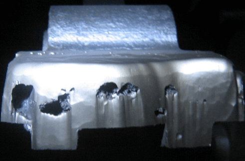 fig.8
fig.8
An additional difficulty in adjusting the supply of coal to the grinding chamber is introduced by such an external factor as the low quality of cast bars made of manganese steels, first of all, the presence of different-sized pores and voids in the working part, leading to the formation of an uneven wear profile (Fig. 8), even in case of uniform supply of coal.
Factor #3 Different intensity and configuration of vortex flows generated in the grinding chamber
Due to the fact that the design features of the grinding chamber allow the formation of lining surfaces of various configurations, the aerodynamic characteristics inside the chamber cavity differ not only for machines at different industrial facilities, but, sometimes, even within the same boiler-turbine shop. Also, the perforation of the disks makes it possible to fix on them a different number of beater holders - 3, 4, 6, 8 and to form a different number of beaters in the mill along the rotor, which also significantly affects the nature of dynamic flows.
There are three schemes for conducting technological tests of new beaters, each of which has its own advantages, disadvantages and methods for compensating for these shortcomings.
| Options | Weight schemes | ||
| Complete | half | alternating | |
| Schematic representation |  |
 |
 |
| Advantages | The test conditions are closest to the operating conditions. | Comparable loads, the same quality of coals. Short test times. | |
| Flaws | Unreliability of data due to incommensurability of loads and quality of coals in the absence of means of individual control over a specific MMT. The duration of the test. | Unreliable data in case of uneven horizontal wear; The occurrence of rotor beating as a result of different wear rates of different groups of beaters. | Unreliable data due to increased wear of more wear-resistant beaters, which take on an increased load. |
| Compensation methods for deficiencies | Statistical. Increased confidence due to more testing and comparison with a statistically defined comparison basis (mean operating period). | The risk of emergencies due to the beating of the rotor cannot be eliminated. Unreliable data due to uneven horizontal wear can be eliminated by alternately loading the same parts with different groups of beaters. | No |
Mechanical properties are revealed when the metal is subjected to tensile, bending or other forces. The mechanical properties of metals are characterized by: 1) tensile strength in kg / mm 2; 2) relative elongation in%; 3) impact strength in kgm / cm 2; 4) hardness; 5) bending angle. The listed basic properties of metals are determined by the following tests: 1) tensile; 2) on the bend; 3) hardness; 4) to strike. All these tests are carried out on metal samples using special machines.
Tensile test. The tensile test determines the tensile strength and relative elongation of the metal.
The tensile strength is the force that must be applied per unit area of the cross section of a metal sample in order to break it.
For tensile testing, samples are made, the shape and dimensions of which are established by GOST 1497-42. tests are carried out on special tensile testing machines. The heads of the sample are fixed in the grips of the machine, after which a load is applied that stretches the sample until failure.
For testing sheet metal, flat specimens are made. Mild steels have a tensile strength of about 40 kg / mm 2 steel of increased strength and special - 150 kg / mm 2.
The relative elongation of mild steel is approximately 20%.
Relative elongation characterizes the ductility of the metal, it decreases with increasing tensile strength.
 Hardness test. To determine the hardness of the metal, a Brinell or Rockwell device is used.
Brinell hardness is determined as follows. A hard steel ball 10.5 or 2.5 mm in diameter is pressed under pressure into the metal to be tested. Then, using a binocular tube, the diameter of the imprint, which was obtained under the ball on the test metal, is measured. Brinell hardness is determined from the diameter of the indentation and according to the corresponding table.
The hardness of some steels in Brinell units:
Mild steel......IV 120-130
High strength steel.... IV 200-300
Hard hardened steels.....IV 500-600
As the hardness increases, the ductility of the metal decreases.
Impact test. This test determines the ability of the metal to withstand impact loads. The impact test determines the impact strength of the metal.
Impact strength is determined by testing samples on special pendulum impact testers. The lower the impact strength, the more brittle and the less reliable such a metal is in operation. The higher the impact strength, the better the metal. Good mild steel has an impact strength of 10-15 kgm/cm 2 .

Bend test. Reinforcement for reinforced concrete structures must have hooks at the ends with a bend angle of up to 180 ° and bends along the length of the reinforcement by 45 and 90 °. Therefore, reinforcing steel is subjected to a cold bend test.
Technological tests establish the ability of reinforcing steel to perceive deformations without violating integrity, i.e. without the appearance of cracks, tears, delaminations in it.


