LED flashlight 1 3W do-it-yourself circuits. Homemade cree LED flashlight
Let's take a look at LED products ranging from the old 5mm LEDs to super-bright high-power LEDs up to 10W.
To choose the “right” flashlight for your needs, you need to understand what kind of LED flashlights are and their characteristics.
What diodes are used in flashlights?
Powerful LED lights began with devices with a 5mm matrix.
LED flashlights in completely different designs, from pocket to camping, became widespread in the mid-2000s. Their price has dropped significantly, and the brightness and long battery life have played a role.
 5mm white ultra-bright LEDs draw 20 to 50 mA of current at a voltage drop of 3.2-3.4 volts. Light intensity - 800 mcd.
They show themselves very well in miniature flashlights-trinkets. The small size allows you to carry such a flashlight with you. They are powered either by "mini-finger" batteries, or from several round "pills". Often used in lighters with a flashlight.
Here are the LEDs Chinese lanterns have been established for many years, but their age is gradually expiring.
In search lights with a large reflector, it is possible to mount dozens of such diodes, but such solutions are gradually fading into the background, and the choice of buyers falls in favor of lights on powerful Cree-type LEDs.
 Search light with 5mm LEDs
 These flashlights run on AA, AAA or rechargeable batteries. They are inexpensive and lose both in brightness and quality to modern flashlights on more powerful crystals, but more on that below.
In the further development of flashlights, manufacturers went through many options, but the market for quality products is occupied by flashlights with powerful matrices or discrete LEDs.
What LEDs are used in powerful flashlights?
Powerful lanterns mean modern lanterns various types ranging from those that are the size of a finger, ending with huge search lights.

In such products in 2017, the Cree brand is relevant. This is the name of an American company. Its products are considered one of the most advanced in the field of LED technology. An alternative are LEDs from the manufacturer Luminus.
Such things are far superior to LEDs from Chinese lanterns.
What are the most commonly installed Cree LEDs in flashlights?
Models are named consisting of three to four characters separated by a hyphen. So diodes Cree XR-E, XR-G, XM-L, XP-E. Models XP-E2, G2 are most often used for small flashlights, while XM-L and L2 are very versatile.
They are used starting from the so-called. EDC flashlights (for everyday wear) are from small flashlights smaller than the palm of your hand, to serious search lights of large size.
Let's look at the characteristics of high-power LEDs for flashlights.
| Name | Cree XM-L T6 | Cree XM-L2 | Cree XP-G2 | Cree XR-E |
| A photo |  |
|||
| U, V | 2,9 | 2,85 | 2,8 | 3,3 |
| I, mA | 700 | 700 | 350 | 350 |
| P, W | 2 | 2 | 1 | 1 |
| Operating temperature, °C | ||||
| Luminous flux, Lm | 280 | 320 | 145 | 100 |
| Luminescence angle, ° | 125 | 125 | 115 | 90 |
| Color rendering index, Ra | 80-90 | 70-90 | 80-90 | 70-90 |
The main characteristic of LEDs for flashlights is the luminous flux. It determines the brightness of your flashlight and the amount of light that the source can give. Different LEDs, consuming the same amount of energy, can differ significantly in brightness.
Consider the characteristics of LEDs in large flashlights, searchlight type :
| Name | ||||
| A photo |  |  |  |  |
| U, V | 5,7; 8,55; 34,2; | 6; 12; | 3,6 | 3,5 |
| I, mA | 1100; 735; 185; | 2500; 1250 | 5000 | 9000...13500 |
| P, W | 6,3 | 8,5 | 18 | 20...40 |
| Operating temperature, °C | ||||
| Luminous flux, Lm | 440 | 510 | 1250 | 2000...2500 |
| Luminescence angle, ° | 115 | 120 | 100 | 90 |
| Color rendering index, Ra | 70-90 | 80-90 | 80-90 |
Sellers often indicate not the full name of the diode, its type and characteristics, but an abbreviated, slightly different alphanumeric marking:
- For XM-L: T5; T6; U2;
- XP-G: R4; R5; S2;
- XP-E: Q5; R2; R;
- for XR-E: P4; Q3; Q5; R.
The lantern can be called just that, “EDC T6 Lantern”, information in such brevity is more than enough.
Flashlight repair
Unfortunately, the price of such flashlights is quite high, as well as the diodes themselves. And it is not always possible to purchase a new flashlight in case of breakage. Let's figure out how to change the LED in the flashlight.
To repair a flashlight, you need a minimum set of tools:
- soldering iron;
- flux;
- solder;
- screwdriver;
- multimeter.
To get to the light source, you need to unscrew the head of the lantern, it is usually fixed on a threaded connection.

In diode test or resistance measurement mode, check if the LED is working properly. To do this, touch the black and red probes to the LED leads, first in one position, and then swap red and black.

If the diode is working, then in one of the positions there will be low resistance, and in the other - high. This way you determine that the diode is good and conducts current in only one direction. During the test, the diode may emit a weak light.
Otherwise, there will be a short circuit or high resistance (open) in both positions. Then you need to replace the diode in the lamp.

Now you need to unsolder the LED from the lamp and, observing the polarity, solder a new one. Be careful when choosing an LED, consider its current consumption and voltage for which it is designed.
If you neglect these parameters - at best, the flashlight will quickly sit down, at worst - the driver will fail.
A driver is a device for powering an LED with a stabilized current from various sources. Drivers are manufactured industrially for power supply from a 220 volt network, from a car electrical network - 12-14.7 volts, from Li-ion batteries, for example, size 18650. Most powerful flashlights are equipped with a driver.
Increasing the power of the flashlight
If you are not satisfied with the brightness of your flashlight or you figured out how to replace the LED in the flashlight and want to upgrade it, before buying heavy-duty models, study the basic principles of LED operation and limitations in their operation.
 Diode matrices do not like overheating - this is the main postulate! And replacing the LED in the flashlight with a more powerful one can lead to such a situation. Pay attention to the models in which more powerful diodes are installed and compare with yours, if they are similar in size and design, change them.
If your flashlight is smaller, additional cooling will be required. We wrote more about making radiators with our own hands.
If you try to install such a giant as the Cree MK-R in a miniature keychain flashlight, it will quickly fail from overheating and it will be a waste of money. A slight increase in power (by a couple of watts) is acceptable without upgrading the flashlight itself.
Otherwise, the process of replacing the brand of LED in a flashlight with a more powerful one is described above.
Lanterns Police
 Police LED flashlight with shocker
 Such flashlights shine brightly and can act as a means of self-defense. However, they also have problems with LEDs.
How to replace the LED in a Police flashlight
Wide the lineup very difficult to cover in one article, but you can give general recommendations for repair.
- When repairing a flashlight with a stun gun, be careful, it is advisable to use rubber gloves to avoid electric shock.
- Lanterns with dust and moisture protection are assembled on a large number of screws. They differ in length, so make notes where you unscrewed one or another screw.
- The optical system of the Police flashlight allows you to adjust the diameter of the light spot. When disassembling on the body, make marks in what position the parts were before removal, otherwise it will be difficult to put the block with the lens back.
Replacing the LED, voltage converter unit, driver, battery is possible using a standard soldering kit.
What LEDs are in Chinese lanterns?
Many products are now bought on aliexpress, where you can find both original products and Chinese copies that do not match the stated description. The price for such devices is comparable to the price of the original.

In a flashlight where the Cree LED is declared, it may not actually be there, at best there will be a frankly different type of diode, at worst one that will be difficult to distinguish from the original outwardly.
 What might this entail? Cheap LEDs are made in low-tech conditions and do not give out the declared power. They have a low efficiency, from which they have increased heating of the case and crystal. As already mentioned, overheating is the worst enemy for LED devices.
This happens because when the semiconductor is heated, the current increases, as a result of which the heating becomes even stronger, the power is released even more, this leads to an avalanche-like breakdown or breakage of the LED.
If you try and spend time searching for information, you can determine the originality of products.
 Compare original and fake cree
 LatticeBright is a Chinese LED manufacturer that makes products very similar to Cree, probably a design match (sarcasm).
 Comparison of the Chinese copy and the original Cree
 On the substrates, these clones look like this. You can see the variety of shapes of LED substrates produced in China.
 Counterfeit detection by substrate for LED
 Fakes are quite skillfully made, many sellers do not indicate this "brand" in the product description and where the LEDs for the lights are made. The quality of such diodes is not the worst among Chinese junk, but far from the original.
Installing an LED instead of an incandescent lamp
Many old things have horse races or lanterns on an incandescent lamp gathering dust and you can easily make it LED. For this there is either turnkey solutions, or self-made.
With a broken light bulb and LEDs, with a little ingenuity and solder, you can make a great replacement.
An iron barrel in this case is needed to improve heat dissipation from the LED. Next, you need to solder all the parts to each other and fix with glue.
When assembling, be careful - avoid shorting the leads, hot glue or heat shrink tubing will help with this. The central contact of the lamp must be soldered - a hole is formed. Pass a resistor lead through it.
Next, you need to solder the free output of the LED to the base, and the resistor to the central contact. For a voltage of 12 volts, you need a 500 Ohm resistor, and for a voltage of 5 V - 50-100 Ohms, for power from a Li-ion 3.7V battery - 10-25 Ohms.
 How to make an LED from an incandescent lamp
 Choosing an LED for a flashlight is much more difficult than replacing it. It is necessary to take into account a lot of parameters: from brightness and scattering angle, to case heating.
In addition, we must not forget about the power supply for the diodes. If you master everything described above, your devices will shine for a long time and with high quality!
IN modern time More and more devices are using lithium-ion batteries as batteries. They do not have a "memory effect", unlike Ni-Cd. They can deliver high current.
I decided to remake two old flashlights for 18650 lithium-ion batteries, since I have a large number of them. Yes, and getting them is not difficult in repair companies that repair laptops.
For alteration, we need a number of components:
- actual flashlights;
- ;
- ;
- plexiglass;
- a piece of thin plastic;
- ;
- wires, hot glue, tools.
Flashlights of a convenient size for installing 18650 batteries in them, in the amount of two pieces. In principle, you can describe the refinement of one flashlight.
I have different charge controller boards. On one Mini-USB, on the second Micro-USB.
These boards can be purchased in China for 15-20 rubles per unit. Also sold in radio stores and radio markets. I have boards without protection (BMS), but we can handle it.

We disassemble the flashlights and take out all of them, except for the switches, LEDs.

Now we take thin plastic, I have ABS from an old battery. It turned out that it is black, but not scary, it will also look great on a blue flashlight.
We cut out the windows so that they fit snugly into the place where the charge plug used to be put forward.

Cut out right size under the window and holes for the connectors of our charge boards. It is not necessary to glue them, they should fit tightly and I will strengthen them later.

Since our boards do not have discharge protection, boards made from mobile phone batteries are used in this situation. You can also buy with protection, but I do not have such in stock now. Therefore, I resort to a slightly laborious solution.

We unsolder the wires from our BMS to the batteries. We put the charge controller boards in place and support them. As a spacer, I used segments of a wine cork. We strengthen everything with hot glue, but it is possible without it.

We unsolder the switches, my switches break the plus. There is a board with an LED on the black flashlight. The switch has two on positions, one of which I put on a single LED, and the second position turns on the main LEDs. There is one switch position on the blue flashlight.

We assemble the flashlights and solder the reflectors and proceed to the next step.
The next step is to cut out two records from transparent plastic, I have this plastic from the CD box. We sandpaper until the surface is dull, so the light from the LED is more pleasant.

We glue it to the place where the engine used to be, with which the network plug was extended. You need to glue on one half of the flashlight. Suddenly you will need to disassemble the flashlight.
A flashlight is a must have in every home. Sometimes the light goes out, or you have to go to a dark basement. In general, such a thing should always be at hand. And it is desirable that it can be stored for a long time without recharging. And then you find out about dead batteries at the most inopportune moment :) For this, we will use a lithium-ion battery, which has a very low self-discharge. In general, for a long time I had a lantern lying idle DiK-5 euro. As a light source, it uses a 2.5v 0.15A incandescent bulb, the power source of which is 3 round disk elements D-0.26. The flashlight initially held a charge for about an hour of continuous operation, but now it does not hold at all and the batteries have oxidized. The light bulb doesn't really shine. In short, you can’t call a good flashlight.
I took it apart, removed all the insides and cut out the plastic partitions with an engraver that fix the batteries. Next, it was decided to replace the light bulb with a 1W (4200k) LED, which fell out of the lamp spotlight because it was a bit crowded there, and the reflector was bad.


Then I borrowed from a broken Nokia cell phone, which they gave me for spare parts, a battery and a connector charger. I calculated the resistor for the LED, since the Battery produces 3.6V, and the voltage of the LED is 3V (in my case).


Since the LED heats up, it needs cooling. I sawed out a piece of aluminum and fixed it on one half of the case, drilled two holes in it for the legs of the LED and inserted it, first insulating each leg with heat shrink tubing. In the photo below - for comparison, the view of a conventional lamp and an LED, in a reflector.

Between the radiator and the LED, I smeared the pad with thermal paste. The toggle switch was taken from a fluorescent lamp. Then I soldered everything and fixed the connector for charging with hot melt adhesive. The battery, although it is 860mAh, lasts for 2.5-3 hours of continuous work.
A flashlight is a necessary thing in every home, you can go down to the basement or go up to the attic with it, take it with you to nature, carry it in the car ... Today on the market you can find a large number of LED lights powered by 3 AA batteries, as a rule they are inexpensive , prices in the region of 100-150 rubles.
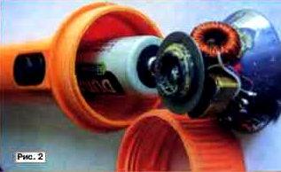
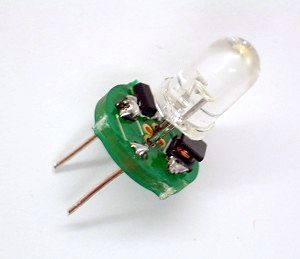
I offer you my idea for altering such a flashlight. We need: a flashlight, a powerful LED 3.6 volts 500mA, white glow (I have a cold light), a 1.5 volt battery and a couple of radio components. We disassemble the lantern and pull out the board with LEDs from there, we don’t need it (but if you want, you can implement the circuit below on the same LEDs, only they consume more current), instead of them we will put our powerful LED, but keep in mind when buying a flashlight the next factor is to easily fit our LED into the lamp housing, this LED with a radiator and looks like this:

These LEDs are still sold without radiators, I advise you not to mess with such, and the price is not much different. Now as for the diagram, you can see it below:
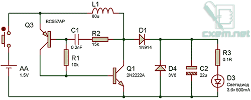
This is a voltage converter circuit, in principle, you don’t need to assemble this circuit, because as a rule such lights run on 3 batteries and the voltage when they are connected in series will be something around 4.5 (if you use simple batteries) and 3.6 Volts if you use 1.2 batteries IN. Below in the archive there is a project in the protes, so you can simulate the circuit on your computer, you can play with the resistor values, or pick up the equivalent load on the output.
I have two options for flashlights, one with a voltage converter, the other without. The scheme uses easily accessible and widespread radio components. I do not recommend deviating from the given ratings in the circuit, the output voltage will depend on the value of the capacitor C1 (can be replaced by 200pF), resistors R2 and R3. D1 in the circuit is a Schottky diode, the circuit works worse with conventional diodes. A zener diode is needed to maintain the voltage at 3.6 volts, without a zener diode, the voltage can rise up to 4 volts. For LEDs, as a rule, the supply voltage range is as follows: 2.7 minimum voltage, 3.3 average, 3.7 maximum direct.
Unfortunately, I started writing the article after I made a flashlight, and I can’t provide a detailed photo report, but I’ll still show a couple of photos.

I did not make a printed circuit board for the circuit, I soldered everything by surface mounting on smd elements, these lights have been working for more than six months, until they failed.
List of radio elements
| Designation | Type | Denomination | Quantity | Note | Shop | My notepad |
|---|---|---|---|---|---|---|
| Q1 | bipolar transistor | 2N2222A | 1 | To notepad | ||
| Q | bipolar transistor | BC557A | 1 | To notepad | ||
| D1 | rectifier diode | 1N914 | 1 | To notepad | ||
| D3 | Light-emitting diode | 3.6V 500mA | 1 | To notepad | ||
| D4 | zener diode | 1N4729A | 1 | To notepad | ||
| C1 | Capacitor | 0.2 nF | 1 | To notepad | ||
| C2 | electrolytic capacitor | 22 uF | 1 | To notepad | ||
| R1 | Resistor | 10 kOhm | 1 | To notepad | ||
| R2 | Resistor | 15 kOhm | 1 | To notepad | ||
| R3 | Resistor | 0.1 ohm | 1 |
We make a flashlight on LEDs with our own hands
LED flashlight with 3V converter for LED 0.3-1.5V 0.3-1.5
VLEDflash light
Usually, a blue or white LED requires 3 - 3.5v to operate, this circuit allows you to power a blue or white LED with low voltage from a single AA battery.Normally, if you want to light up a blue or white LED you need to provide it with 3 - 3.5 V, like from a 3 V lithium coin cell.
Details:
Light-emitting diode
Ferrite ring (~10 mm diameter)
Winding wire (20 cm)
1kΩ resistor
N-P-N transistor
Battery
Parameters of the used transformer:
The winding going to the LED has ~45 turns wound with 0.25mm wire.
The winding going to the base of the transistor has ~30 turns of 0.1mm wire.
The base resistor in this case has a resistance of about 2K.
Instead of R1, it is desirable to put a tuning resistor, and achieve a current through the diode ~ 22mA, with a fresh battery, measure its resistance, then replacing it with a constant resistor of the received value.
The assembled circuit must work immediately.
There are only 2 reasons why the scheme will not work.
1. the ends of the winding are mixed up.
2. too few turns of the base winding.
Generation disappears, with the number of turns<15.
 Put the pieces of wire together and wind around the ring.
Connect the two ends of different wires together.
The circuit can be placed inside a suitable enclosure.
The introduction of such a circuit into a flashlight operating from 3V significantly extends the duration of its operation from one set of batteries.
Variant of execution of a lamp from one battery 1,5v.


The transistor and resistance are placed inside the ferrite ring


White LED powered by a dead AAA battery
Modernization option "flashlight - handle"
 The excitation of the blocking generator shown in the diagram is achieved by a transformer connection at T1. The voltage pulses that occur in the right (according to the scheme) winding are added to the voltage of the power source and fed to the VD1 LED. Of course, it would be possible to exclude the capacitor and resistor in the base circuit of the transistor, but then VT1 and VD1 may fail when using branded batteries with low internal resistance. The resistor sets the operating mode of the transistor, and the capacitor passes the RF component.
The circuit used a KT315 transistor (as the cheapest, but any other with a cutoff frequency of 200 MHz or more), an ultra-bright LED. For the manufacture of a transformer, a ferrite ring is required (approximate size 10x6x3 and a permeability of about 1000 HH). The wire diameter is about 0.2-0.3 mm. Two coils of 20 turns each are wound on the ring.
If there is no ring, then a cylinder similar in volume and material can be used. You just have to wind 60-100 turns for each of the coils.
Important point : you need to wind the coils in different directions.
Flashlight photos:
the switch is located in the "fountain pen" button, and the gray metal cylinder conducts current.

We make a cylinder according to the size of the battery.


It can be made from paper, or a piece of any rigid tube can be used.
We make holes along the edges of the cylinder, wrap it with tinned wire, pass the ends of the wire into the holes. We fix both ends, but leave a piece of conductor at one of the ends: so that you can connect the converter to the spiral.
A ferrite ring would not fit into a lantern, so a cylinder of similar material was used.

Cylinder from an inductor from an old TV.
The first coil is about 60 turns.
Then the second, winds in the opposite direction again 60 or so. The threads are held together with glue.
We assemble the converter:

Everything is located inside our case: We unsolder the transistor, the resistor capacitor, solder the spiral on the cylinder, and the coil. The current in the coil windings must go in different directions! That is, if you wound all the windings in one direction, then swap the conclusions of one of them, otherwise generation will not occur.
It turned out the following:

We insert everything inward, and use nuts as side plugs and contacts.
We solder the coil leads to one of the nuts, and the VT1 emitter to the other. Glue. we mark the conclusions: where we will have an output from the coils, we put “-”, where the output from the transistor with the coil we put “+” (so that everything is like in a battery).
Now you should make a "lamp diode".

Attention: on the base should be minus the LED.
Assembly:
 As is clear from the figure, the converter is a "substitute" for the second battery. But unlike it, it has three points of contact: with the plus of the battery, with the plus of the LED, and the common body (through the spiral).
Its location in the battery compartment is specific: it must be in contact with the positive of the LED.
Modern flashlightwith the mode of operation of the LED powered by constant stabilized current.

The current stabilizer circuit works as follows:
When power is applied to the circuit, transistors T1 and T2 are locked, T3 is open, because an unlocking voltage is applied to its gate through resistor R3. Due to the presence of an inductor L1 in the LED circuit, the current increases smoothly. As the current in the LED circuit increases, the voltage drop across the R5-R4 chain increases, as soon as it reaches about 0.4V, transistor T2 opens, followed by T1, which in turn closes the current switch T3. The increase in current stops, a self-induction current arises in the inductor, which begins to flow through the diode D1 through the LED and the chain of resistors R5-R4. As soon as the current decreases below a certain threshold, transistors T1 and T2 will close, T3 will open, which will lead to a new cycle of energy accumulation in the inductor. In normal mode, the oscillatory process occurs at a frequency of the order of tens of kilohertz.
About details:
Instead of the IRF510 transistor, you can use the IRF530, or any n-channel field-effect key transistor for a current of more than 3A and a voltage of more than 30 V.
Diode D1 must necessarily be with a Schottky barrier for a current of more than 1A, if you put an ordinary even high-frequency type KD212, the efficiency will drop to 75-80%.
The inductor is homemade, it is wound with a wire no thinner than 0.6 mm, better with a bundle of several thinner wires. About 20-30 turns of wire on the B16-B18 armor core are required with a non-magnetic gap of 0.1-0.2 mm or close to 2000NM ferrite. If possible, the thickness of the non-magnetic gap is selected experimentally according to the maximum efficiency of the device. Good results can be obtained with ferrites from imported inductors installed in switching power supplies, as well as in energy-saving lamps. Such cores have the form of a thread spool, do not require a frame and a non-magnetic gap. Coils on toroidal cores made of pressed iron powder, which can be found in computer power supplies (they are wound with output filter inductors), work very well. The non-magnetic gap in such cores is evenly distributed in volume due to the production technology.
The same stabilizer circuit can also be used in conjunction with other batteries and batteries of galvanic cells with a voltage of 9 or 12 volts without any change in the circuit or cell ratings. The higher the supply voltage, the less current the flashlight will consume from the source, its efficiency will remain unchanged. The stabilization current is set by resistors R4 and R5.
If necessary, the current can be increased up to 1A without the use of heat sinks on the parts, only by selecting the resistance of the setting resistors.
The charger for the battery can be left "native" or assembled according to any of the known schemes, or even use an external one to reduce the weight of the flashlight.
LED flashlight from calculator B3-30
The converter is based on the B3-30 calculator circuit, in the switching power supply of which a transformer with a thickness of only 5 mm is used, which has two windings. Using a pulse transformer from an old calculator made it possible to create an economical LED flashlight.
The result is a very simple circuit.
 The voltage converter is made according to the scheme of a single-cycle generator with inductive feedback on a transistor VT1 and a transformer T1. The impulse voltage from the windings 1-2 (according to the B3-30 calculator circuit diagram) is rectified by the VD1 diode and fed to the super-bright HL1 LED. Capacitor C3 filter. The design is based on a Chinese-made flashlight designed to install two AA batteries. The transducer is mounted on a printed circuit board made of one-sided foil-coated fiberglass with a thickness of 1.5 mmfig.2sizes that replace one battery and inserted into the flashlight instead of it. A contact made of double-sided foil fiberglass with a diameter of 15 mm is soldered to the end of the board marked with a “+” sign, both sides are connected by a jumper and soldered.
After installing all the parts on the board, the “+” end contact and the T1 transformer are filled with hot glue to increase strength. The layout of the lantern is shown infig.3and in a particular case depends on the type of lamp used. In my case, no modification of the lamp was required, the reflector has a contact ring, to which the negative output of the printed circuit board is soldered, and the board itself is attached to the reflector with hot glue. The printed circuit board assembly with the reflector is inserted instead of one battery and clamped with a cover.
 The voltage converter uses small parts. Resistors of the MLT-0.125 type, capacitors C1 and C3 are imported, up to 5 mm high. Diode VD1 type 1N5817 with a Schottky barrier, in its absence, you can use any rectifier diode that is suitable for the parameters, preferably germanium due to the lower voltage drop across it. A properly assembled converter does not need to be adjusted if the transformer windings are not reversed, otherwise swap them. In the absence of the above transformer, you can make it yourself. Winding is carried out on a ferrite ring of size K10 * 6 * 3 with a magnetic permeability of 1000-2000. Both windings are wound with PEV2 wire with a diameter of 0.31 to 0.44 mm. The primary winding has 6 turns, the secondary 10 turns. After installing such a transformer on the board and checking its performance, it should be fixed on it with hot glue.
Flashlight tests with an AA battery are presented in Table 1.
The test used the cheapest AA battery costing only 3 rubles. The initial voltage under load was 1.28 V. At the output of the converter, the voltage measured on a superbright LED was 2.83 V. The brand of the LED is unknown, the diameter is 10 mm. The total current consumption is 14 mA. The total operating time of the flashlight was 20 hours of continuous operation.
When the voltage on the battery drops below 1V, the brightness drops noticeably.
| Time, h | V batteries, V | V conversion, V |
| 0 | 1,28 | 2,83 |
| 2 | 1,22 | 2,83 |
| 4 | 1,21 | 2,83 |
| 6 | 1,20 | 2,83 |
| 8 | 1,18 | 2,83 |
| 10 | 1,18 | 2.83 |
| 12 | 1,16 | 2.82 |
| 14 | 1,12 | 2.81 |
| 16 | 1,11 | 2.81 |
| 18 | 1,11 | 2.81 |
| 20 | 1,10 | 2.80 |
Homemade flashlight with LEDs
The basis is a flashlight "VARTA" powered by two AA batteries:
Since diodes have a highly non-linear IV characteristic, it is necessary to equip the flashlight with a circuit for operating on LEDs, which will provide a constant brightness of the glow as the battery is discharged and will remain operational at the lowest possible supply voltage.
The heart of the voltage regulator is the MAX756 micropower DC/DC boost converter.
According to the declared characteristics, it works when the input voltage drops to 0.7V.
Switching scheme - typical:

 Mounting is carried out in a hinged way.
Electrolytic capacitors - tantalum CHIP. They have a low series resistance, which improves efficiency somewhat. Schottky diode - SM5818. Chokes had to be connected in parallel, because. there was no suitable value. Capacitor C2 - K10-17b. LEDs - superbright white L-53PWC "Kingbright".
As you can see in the figure, the whole circuit easily fit into the empty space of the light emitting node.
The output voltage of the stabilizer in this switching circuit is 3.3V. Since the voltage drop across the diodes in the nominal current range (15-30mA) is about 3.1V, the extra 200mV had to be extinguished by a resistor connected in series with the output.
In addition, a small series resistor improves load linearity and circuit stability. This is due to the fact that the diode has a negative TCR, and when it is heated, the direct voltage drop decreases, which leads to a sharp increase in current through the diode when it is powered from a voltage source. It was not necessary to equalize the currents through the diodes connected in parallel - no difference in brightness was observed by eye. Moreover, the diodes were of the same type and taken from the same box.
Now about the design of the light emitter. As you can see in the photos, the LEDs in the circuit are not soldered tightly, but are a removable part of the structure.

 The native light bulb is gutted, and 4 cuts are made in the flange from 4 sides (one was already there). 4 LEDs are arranged symmetrically in a circle. The positive leads (according to the diagram) are soldered to the base near the cuts, and the negative leads are inserted from the inside into the central hole of the base, cut off and also soldered. "Lamp diode", inserted in place of a conventional incandescent light bulb.
Testing:
The stabilization of the output voltage (3.3V) continued until the supply voltage dropped to ~1.2V. The load current in this case was about 100mA (~ 25mA per diode). Then the output voltage began to gradually decrease. The circuit has switched to a different mode of operation, in which it no longer stabilizes, but outputs everything it can. In this mode, it worked up to a supply voltage of 0.5V! The output voltage at the same time dropped to 2.7V, and the current from 100mA to 8mA.
A little about efficiency.
 The efficiency of the circuit is about 63% with fresh batteries. The fact is that the miniature chokes used in the circuit have an extremely high ohmic resistance - about 1.5 ohm
The solution is a µ-permalloy ring with a permeability of about 50.
40 turns of PEV-0.25 wire, in one layer - it turned out about 80 μG. The active resistance is about 0.2 Ohm, and the saturation current, according to calculations, is more than 3A. We change the output and input electrolyte to 100 microfarads, although without prejudice to efficiency it can be reduced to 47 microfarads.
Scheme of the LED lampon DC/DC converter from Analog Device - ADP1110.

Standard typical connection diagram of ADP1110.
This converter chip, according to the manufacturer's specifications, is available in 8 versions:
| Model | Output voltage |
| ADP1110AN | Adjustable |
| ADP1110AR | Adjustable |
| ADP1110AN-3.3 | 3.3V |
| ADP1110AR-3.3 | 3.3V |
| ADP1110AN-5 | 5V |
| ADP1110AR-5 | 5V |
| ADP1110AN-12 | 12V |
| ADP1110AR-12 | 12V |
Microcircuits with indices "N" and "R" differ only in the type of package: R is more compact.
If you bought a chip with an index of -3.3, you can skip the next paragraph and go to the "Details" item.
If not, I present to your attention another scheme:

It adds two parts to get the required 3.3 volts output to power the LEDs.
The circuit can be improved by taking into account that the LEDs need a current source, not a voltage source, to operate. Changes in the circuit so that it would give out 60mA (20 for each diode), and the diodes will automatically set the voltage to us, the same 3.3-3.9V.

resistor R1 is used to measure the current. The converter is designed in such a way that when the voltage at the FB (Feed Back) pin exceeds 0.22V, it will finish increasing the voltage and current, which means that the value of the resistance R1 is easy to calculate R1 = 0.22V / In, in our case 3.6Ω. Such a circuit helps to stabilize the current, and automatically select the required voltage. Unfortunately, voltage will drop across this resistance, which will lead to a decrease in efficiency, however, practice has shown that it is less than the excess that we chose in the first case. I measured the output voltage and it was 3.4 - 3.6V. The parameters of the diodes in such an inclusion should also be as similar as possible, otherwise the total current of 60mA was not distributed equally between them, and again we will get different luminosity.
Details
1. A choke will fit any 20 to 100 microhenry with a small (less than 0.4 ohm) resistance. The diagram indicates 47 μH. You can make it yourself - wind about 40 turns of PEV-0.25 wire on a µ-permalloy ring with a permeability of about 50, size 10x4x5.
2. Schottky diode. 1N5818, 1N5819, 1N4148 or equivalent. Analog Device DOES NOT RECOMMEND the use of the 1N4001
3. Capacitors. 47-100 microfarads at 6-10 volts. It is recommended to use tantalum.
4. Resistors. A power of 0.125 watts with a resistance of 2 ohms, possibly 300 kΩ and 2.2 kΩ.
5. LEDs. L-53PWC - 4 pieces.
Voltage converter for powering a white LED DFL-OSPW5111P with a brightness of 30 cd at a current of 80 mA and a radiation pattern width of about 12°.
The current consumed from a battery with a voltage of 2.41V is 143mA; in this case, a current of about 70 mA flows through the LED at a voltage of 4.17 V on it. The converter operates at a frequency of 13 kHz, the electrical efficiency is about 0.85.
Transformer T1 is wound on an annular magnetic circuit of size K10x6x3 made of ferrite 2000NM.
The primary and secondary windings of the transformer are wound simultaneously (i.e., in four wires).
The primary winding contains - 2x41 turns of wire PEV-2 0.19,
The secondary winding contains - 2x44 turns of wire PEV-2 0.16.
After winding, the winding leads are connected in accordance with the diagram.
Transistors KT529A of the p-n-p structure can be replaced with KT530A of the n-p-n structure, in this case it is necessary to change the polarity of connecting the GB1 battery and the HL1 LED.
Details are placed on the reflector using hanging mounting. Pay attention to the fact that the contact of the parts with the tin plate of the flashlight, which supplies the “minus” of the GB1 battery, is excluded. The transistors are fastened together with a thin brass clamp, which provides the necessary heat removal, and then glued to the reflector. The LED is placed instead of the incandescent lamp so that it protrudes 0.5 ... 1 mm from the socket for its installation. This improves heat dissipation from the LED and simplifies its installation.
When first turned on, battery power is supplied through a resistor with a resistance of 18 ... 24 Ohms so as not to damage the transistors if the terminals of the transformer T1 are connected incorrectly. If the LED does not shine, it is necessary to swap the extreme terminals of the primary or secondary winding of the transformer. If this does not lead to success, check the serviceability of all elements and the correct installation.
Voltage converter for powering an industrial design LED lamp.

Voltage converter for powering the LED lamp
 The circuit is taken from the Zetex manual for the use of ZXSC310 microcircuits.
ZXSC310- LED driver chip.
FMMT 617 or FMMT 618.
Schottky diode- almost any brand.
Capacitors C1 = 2.2uF and C2 = 10uFfor surface mounting, 2.2 uF is the value recommended by the manufacturer, and C2 can be set from about 1 to 10 uF
Inductor 68 microhenries at 0.4 A
 The inductance and resistor are installed on one side of the board (where there is no print), all other parts are on the other. The only trick is making a 150 milliohm resistor. It can be made from 0.1 mm iron wire, which can be obtained by unwinding the cable. The wire should be annealed on a lighter, carefully wiped with a fine sandpaper, tinned the ends and soldered a piece about 3 cm long into the holes on the board. Further, in the tuning process, it is necessary, by measuring the current through the diodes, to move the wire, while heating the place of its soldering to the board with a soldering iron.
Thus, something like a rheostat is obtained. Having achieved a current of 20 mA, the soldering iron is removed, and an unnecessary piece of wire is cut off. The author came out with a length of about 1 cm.
Flashlight on power source

Rice. 3.A flashlight on a current source, with automatic current equalization in the LEDs, so that the LEDs can be with any spread of parameters (the VD2 LED sets the current that the transistors VT2, VT3 repeat, so the currents in the branches will be the same)
Transistors, of course, should also be the same, but the spread of their parameters is not so critical, so you can take either discrete transistors, or if you can find three integrated transistors in one package, their parameters are as close as possible. Play with the placement of the LEDs, you need to choose a pair of LED-transistor so that the output voltage is minimal, this will increase the efficiency.
The introduction of transistors evened out the brightness, but they have resistance and voltage drops on them, which forces the converter to increase the output level to 4V, to reduce the voltage drop across the transistors, you can propose a circuit in Fig. 4, this is a modified current mirror, instead of the reference voltage Ube = 0.7V in the circuit in Fig. 3, you can use the 0.22V source built into the converter, and maintain it in the VT1 collector using an op-amp, also built into the converter.

Rice. 4.Flashlight on a power source, with automatic current equalization in the LEDs, and with improved efficiency
Because the output of the opamp is of the “open collector” type; it must be “pulled up” to the power supply, which makes the resistor R2. Resistors R3, R4 act as a voltage divider at point V2 by 2, so the opamp will maintain a voltage of 0.22 * 2 = 0.44V at point V2, which is 0.3V less than in the previous case. It is impossible to take a divider even less in order to lower the voltage at point V2. the bipolar transistor has a resistance Rke and during operation, the voltage Uke will drop on it, so that the transistor works correctly V2-V1 must be greater than Uke, for our case 0.22V is enough. However, bipolar transistors can be replaced with field-effect transistors, in which the drain-to-source resistance is much less, this will make it possible to reduce the divider, so that the difference V2-V1 is completely insignificant.
Throttle.The inductor must be taken with a minimum resistance, special attention should be paid to the maximum allowable current, it should be of the order of 400 -1000 mA.
The rating doesn't matter as much as the maximum current, so Analog Devices recommends something between 33 and 180uH. In this case, theoretically, if you do not pay attention to the dimensions, then the larger the inductance, the better in all respects. However, in practice this is not entirely true, because. we have a non-ideal coil, it has active resistance and is not linear, in addition, the key transistor at low voltages will no longer give out 1.5A. Therefore, it is better to try several coils of different types, designs and different ratings in order to choose a coil with the highest efficiency and the smallest minimum input voltage, i.e. the coil with which the flashlight will glow for as long as possible.
Capacitors.C1 can be anything. C2 is better to take tantalum because. it has a small resistance, which increases the efficiency.
Schottky diode.Any for current up to 1A, preferably with minimal resistance and minimal voltage drop.
Transistors.Any with collector current up to 30 mA, coefficient current amplification of the order of 80 with a frequency of up to 100 MHz, KT318 is suitable.
LEDs.You can white NSPW500BS with a glow of 8000mCd from Power Light Systems.
Voltage transformerADP1110, or its replacement ADP1073, to use it, the circuit in Fig. 3 will need to be changed, take a 760μG inductor, and R1 = 0.212 / 60mA = 3.5Ω.
Lantern on ADP3000-ADJ
Parameters:
Power supply 2.8 - 10 V, efficiency approx. 75%, two brightness modes - full and half.
The current through the diodes is 27 mA, in half brightness mode - 13 mA.
In order to obtain high efficiency, it is desirable to use chip components in the circuit.
A properly assembled circuit does not need to be configured.
The disadvantage of the circuit is the high (1.25V) voltage at the FB input (pin 8).
Currently, DC / DC converters with an FB voltage of about 0.3V are being produced, in particular, by Maxim, on which it is realistic to achieve an efficiency above 85%.

Scheme of a lantern on Kr1446PN1.

Resistors R1 and R2 - current sensor. Operational amplifier U2B - amplifies the voltage taken from the current sensor. The gain = R4 / R3 + 1 and is approximately 19. The gain is required so that when the current through the resistors R1 and R2 is 60 mA, the output voltage opens the transistor Q1. By changing these resistors, you can set other stabilization current values.
In principle, an operational amplifier can be omitted. It’s just that instead of R1 and R2 one 10 Ohm resistor is placed, from it the signal through the 1kOhm resistor is fed to the base of the transistor and that’s it. But. This will lead to a decrease in efficiency. On a 10 ohm resistor at a current of 60 mA, 0.6 volts - 36 mW is wasted in vain. In the case of using an operational amplifier, the losses will be:
on a 0.5 Ohm resistor at a current of 60 mA = 1.8 mW + the consumption of the op-amp itself is 0.02 mA, let at 4 Volts = 0.08 mW
= 1.88 mW - significantly less than 36 mW.
About components.
In place of KR1446UD2, any low-power op-amp with a low minimum supply voltage can work, OP193FS would be better, but it is quite expensive. Transistor in SOT23 package. The polar capacitor is smaller - type SS at 10 Volts. Inductance CW68 100uH for 710mA. Although the cutoff current of the converter is 1 A, it works normally. It has the best efficiency. I selected the LEDs for the most identical voltage drop at a current of 20 mA. Assembled a flashlight in a case for two AA batteries. I shortened the place for the batteries to fit the size of AAA batteries, and in the freed space I assembled this circuit by surface mounting. A case for three AA batteries will work well. You will need to install only two, and place the scheme in place of the third.
The efficiency of the resulting device.
Input U I P Output U I P Efficiency
Volt mA mW Volt mA mW %
3.03 90 273 3.53 62 219 80
1.78 180 320 3.53 62 219 68
1.28 290 371 3.53 62 219 59
Replacing the light bulb of the flashlight “Zhuchok” with a module from the companyLuxionLumiledLXHL-NW 98.
We get a dazzlingly bright flashlight, with a very light press (compared to a light bulb).


Modification scheme and module parameters.
StepUP DC-DC converters ADP1110 from Analog devices.


Power supply: 1 or 2 batteries 1.5V operability is maintained up to Uin.=0.9V
Consumption:
*with open switch S1 = 300mA
*with switch closed S1 = 110mA
LED electronic flashlight
Powered by just one AA or AAA AA battery on a microcircuit (KR1446PN1), which is a complete analogue of the MAX756 (MAX731) microcircuit and has almost identical characteristics.

The flashlight is taken as a basis, in which two AA batteries (accumulators) are used as a power source.
The converter board is placed in the lantern instead of the second battery. On one end of the board, a tinned sheet contact is soldered to power the circuit, and on the other, an LED. A circle of the same tin is put on the conclusions of the LED. The diameter of the circle should be slightly larger than the diameter of the reflector base (by 0.2-0.5 mm), into which the cartridge is inserted. One of the terminals of the diode (negative) is soldered to the mug, the second (positive) passes through and is insulated with a piece of PVC or fluoroplastic tubing. The purpose of the circle is twofold. It provides the structure with the necessary rigidity and at the same time serves to close the negative contact of the circuit. A lamp with a cartridge is removed from the lantern in advance and a circuit with an LED is placed instead. Before installation on the board, the LED leads are shortened in such a way as to ensure a tight, play-free fit “in place”. Typically, the length of the leads (excluding soldering to the board) is equal to the length of the protruding part of the fully screwed lamp base.
The connection diagram of the board and the battery is shown in fig. 9.2.
Next, the lantern is assembled and its performance is checked. If the circuit is assembled correctly, then no settings are required.
The design uses standard installation elements: capacitors of the K50-35 type, EC-24 chokes with an inductance of 18-22 μH, LEDs with a brightness of 5-10 cd with a diameter of 5 or 10 mm. Of course, it is also possible to use other LEDs with a supply voltage of 2.4-5 V. The circuit has a sufficient power reserve and allows you to power even LEDs with a brightness of up to 25 cd!
On some test results of this design.
The lantern modified in this way worked with a “fresh” battery without interruption, in the switched on state, for more than 20 hours! For comparison, the same flashlight in the "standard" configuration (that is, with a lamp and two "fresh" batteries from the same batch) worked for only 4 hours.
And one more important point. If rechargeable batteries are used in this design, it is easy to monitor the state of their discharge level. The fact is that the converter on the KR1446PN1 chip starts stably at an input voltage of 0.8-0.9 V. And the glow of the LEDs is consistently bright until the voltage on the battery has reached this critical threshold. The lamp will still burn at this voltage, of course, but it is hardly possible to speak of it as a real source of light.
Rice. 9.2Figure 9.3


The printed circuit board of the device is shown in fig. 9.3, and the location of the elements - in fig. 9.4.
Turning the flashlight on and off with one button
The circuit is assembled on a CD4013 D-trigger chip and an IRF630 field effect transistor in the "off" mode. the current consumption of the circuit is practically 0. For stable operation of the D-flip-flop, a filter resistor and a capacitor are connected to the input of the microcircuit, their function is to eliminate contact bounce. It is better not to connect unused microcircuit pins anywhere. The microcircuit operates from 2 to 12 volts, any powerful field-effect transistor can be used as a power switch, because. the drain-source resistance of the field-effect transistor is negligible and does not load the output of the microcircuit.
CD4013A in SO-14 package, analogue to K561TM2, 564TM2
Simple generator circuits.
 Allow to feed the LED with ignition voltage 2-3V from 1-1.5V. Short pulses of increased potential open the p-n junction. The efficiency of course decreases, but this device allows you to "squeeze out" almost all of its resource from an autonomous power source.
Wire 0.1 mm - 100-300 turns with a tap from the middle, wound on a toroidal ring.

Dimmable LED flashlight with beacon mode
 The power supply of the microcircuit - a generator with an adjustable duty cycle (K561LE5 or 564LE5) that controls the electronic key, in the proposed device is carried out from a step-up voltage converter, which allows you to power the lamp from one galvanic cell 1.5.
The converter is made on transistors VT1, VT2 according to the transformer oscillator circuit with positive current feedback.
The oscillator circuit with an adjustable duty cycle on the K561LE5 chip mentioned above has been slightly modified in order to improve the linearity of current regulation.
The minimum current consumption of the flashlight with six parallel-connected super-bright L-53MWC white LEDs from Kingbnght is 2.3 mA. The dependence of the current consumption on the number of LEDs is directly proportional.
The "Beacon" mode, when the LEDs flash brightly at a low frequency and then go out, is implemented when the brightness control is set to maximum and the flashlight is turned on again. The desired frequency of light flashes is regulated by the selection of the capacitor C3.
The flashlight remains operational when the voltage drops to 1.1v, although the brightness decreases significantly
A field-effect transistor with an insulated gate KP501A (KR1014KT1V) was used as an electronic key. In terms of the control circuit, it is in good agreement with the K561LE5 microcircuit. The KP501A transistor has the following limiting parameters, the drain-source voltage is 240 V; gate-source voltage - 20 V. drain current - 0.18 A; power - 0.5 W
It is permissible to connect transistors in parallel, preferably from the same batch. Possible replacement - KP504 with any letter index. For field-effect transistors IRF540, the supply voltage of the DD1. generated by the converter must be increased to 10 V
In a lamp with six L-53MWC LEDs connected in parallel, the current consumption is approximately equal to 120 mA when the second transistor is connected in parallel to VT3 - 140 mA
Transformer T1 is wound on a ferrite ring 2000NM K10-6 "4.5. The windings are wound in two wires, and the end of the first winding is connected to the beginning of the second winding. The primary winding contains 2-10 turns, the secondary - 2 * 20 turns Wire diameter - 0.37 mm. brand - PEV-2. The inductor is wound on the same magnetic circuit without a gap with the same wire in one layer, the number of turns is 38. The inductance of the inductor is 860 μH


Converter circuit for LED from 0.4 to 3V- powered by one AAA battery. This flashlight increases the input voltage to the required voltage with a simple DC-DC converter.


The output voltage is approximately 7 watts (depending on the voltage of the installed LEDs).
Building the LED Head Lamp


As for the transformer in the DC-DC converter. You must make it yourself. The image shows how to assemble the transformer.

Another version of converters for LEDs _http://belza.cz/ledlight/ledm.htm


Flashlight on a lead-acid sealed battery with a charger.
Lead acid sealed batteries are currently the cheapest. The electrolyte in them is in the form of a gel, so the batteries allow operation in any spatial position and do not produce any harmful fumes. They are characterized by great durability, if you do not allow deep discharge. Theoretically, they are not afraid of overcharging, but this should not be abused. Batteries can be recharged at any time without waiting for them to be completely discharged.
Lead-acid sealed batteries are suitable for use in portable flashlights used in the household, in summer cottages, and in production.

Fig.1. Diagram of an electric lantern
The electrical circuit diagram of a flashlight with a charger for a 6-volt battery, which allows in a simple way to prevent deep discharge of the battery and thus increase its service life, is shown in the figure. It contains a factory-made or self-made transformer power supply and a charger-switching device mounted in the lamp housing.
In the author's version, a standard block designed to power modems is used as a transformer unit. The output AC voltage of the block is 12 or 15 V, the load current is 1 A. There are also such blocks with built-in rectifiers. They are also suitable for this purpose.
The alternating voltage from the transformer unit is supplied to the charging and switching device, which contains a plug for connecting the charger X2, a diode bridge VD1, a current stabilizer (DA1, R1, HL1), a GB battery, a toggle switch S1, an emergency power button S2, an incandescent lamp HL2. Each time the switch S1 is turned on, the battery voltage is supplied to the relay K1, its contacts K1.1 close, supplying current to the base of the transistor VT1. The transistor turns on by passing current through the lamp HL2. The lamp is turned off by switching the toggle switch S1 to its original position, in which the battery is disconnected from the winding of relay K1.
The allowable battery discharge voltage is selected at the level of 4.5 V. It is determined by the turn-on voltage of relay K1. You can change the allowable value of the discharge voltage using the resistor R2. With an increase in the value of the resistor, the allowable discharge voltage increases, and vice versa. If the battery voltage is below 4.5 V, then the relay will not turn on, therefore, voltage will not be applied to the base of the transistor VT1, which turns on the HL2 lamp. This means that the battery needs to be charged. At a voltage of 4.5 V, the illumination created by the flashlight is not bad. In case of emergency, you can turn on the flashlight at low voltage with the S2 button, provided that the S1 toggle switch is first turned on.
A constant voltage can also be applied to the input of the charging-switching device, without paying attention to the polarity of the connected devices.
To transfer the lamp to the charge mode, it is necessary to dock the X1 socket of the transformer unit with the X2 plug located on the lamp body, and then plug the plug (not shown in the figure) of the transformer unit into the 220 V network.
In the above embodiment, a 4.2 Ah battery is used. Therefore, it can be charged with a current of 0.42 A. The battery is charged with direct current. The current stabilizer contains only three parts: an integrated voltage regulator DA1 type KR142EN5A or imported 7805, an HL1 LED and a resistor R1. The LED, in addition to working in a current stabilizer, also performs the function of an indicator of the battery charge mode.
Setting up the electrical circuit of the flashlight is reduced to adjusting the current of the battery charge. The charging current (in amperes) is usually chosen ten times less than the numerical value of the battery capacity (in ampere-hours).
For tuning, it is best to assemble the current stabilizer circuit separately. Instead of a battery load, connect an ammeter for a current of 2 ... 5 A to the connection point of the LED cathode and resistor R1. By selecting resistor R1, set the calculated charge current using the ammeter.
Relay K1 - reed switch RES64, passport RS4.569.724. The HL2 lamp consumes a current of approximately 1A.
The KT829 transistor can be used with any letter index. These transistors are composite and have a high current gain of 750. This should be taken into account in case of replacement.
In the author's version, the DA1 chip is installed on a standard ribbed heatsink with dimensions of 40x50x30 mm. Resistor R1 consists of two 12W wirewound resistors connected in series.
Schemes:


REPAIR OF LED FLASHLIGHT
 Part ratings (C, D, R)
C = 1 uF. R1 = 470 kOhm. R2 = 22 kOhm.
1D, 2D - KD105A (admissible voltage 400V limit current 300 mA.)
Provides:
charging current = 65 - 70mA.
voltage = 3.6V.

LED Treiber PR4401 SOT23


Here you can see what the results of the experiment led to.
The circuit offered to your attention was used to power an LED flashlight, recharge a mobile phone from two metal hydrite batteries, when creating a microcontroller device, a radio microphone. In each case, the operation of the circuit was flawless. The list where you can use the MAX1674 can be continued for a long time.
The easiest way to get a more or less stable current through the LED is to connect it to the unregulated power circuit through a resistor. Keep in mind that the supply voltage must be at least twice the operating voltage of the LED. The current through the LED is calculated by the formula:
I led \u003d (Umax. supply - U working diode) : R1
This scheme is extremely simple and in many cases justified, but it should be used where there is no need to save electricity, and there are no high requirements for reliability.
More stable circuits - based on linear stabilizers:
As stabilizers, it is better to choose adjustable, or fixed voltage, but it should be as close as possible to the voltage on the LED or a string of LEDs connected in series.
Stabilizers like LM 317 are very suitable.
German text:
iel war es, mit nur einer NiCd-Zelle (AAA, 250mAh) eine der neuen ultrahellen LEDs mit 5600mCd zu betreiben. Diese LEDs benötigen 3,6V/20mA. Ich habe Ihre Schaltung zunächst unverändert übernommen, als Induktivität hatte ich allerdings nur eine mit 1,4mH zur Hand. Die Schaltung lief auf Anhieb! Allerdings ließ die Leuchtstärke doch noch zu wünschen übrig. Mehr zufällig stellte ich fest, dass die LED extrem heller wurde, wenn ich ein Spannungsmessgerät parallel zur LED schaltete!??? Tatsächlich waren es nur die Messschnüre, bzw. deren Kapazität, die den Effekt bewirkten. Mit einem Oszilloskop konnte ich dann feststellen, dass in dem Moment die Frequenz stark anstieg. Hm, also habe ich den 100nF-Condensator gegen einen 4.7nF Typ ausgetauscht und schon war die Helligkeit wie gewünscht. Anschließend habe ich dann nur noch durch Ausprobieren die beste Spule aus meiner Sammlung gesucht... Das beste Ergebnis hatte ich mit einem alten Sperrkreis für den 19KHz Pilotton (UKW), aus dem ich die Kreiskapazität entfernt habe. Und hier ist sie nun, die Mini-Taschenlampe:
Sources:
http://pro-radio.ru/
http://radiokot.ru/