An example of calculating a triangular truss. How to correctly calculate and mount trusses from a profile pipe with your own hands? Farm Calculator
Using a profile pipe for mounting trusses, you can create structures designed for high loads. Light metal structures are suitable for the construction of structures, the arrangement of frames for chimneys, the installation of roof supports and canopies. The type and dimensions of farms are determined depending on the specifics of use, whether it is a household or an industrial sector. It is important to correctly calculate the farm from profile pipe Otherwise, the design may not withstand the operational loads.
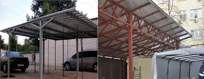
Canopy of arched trusses
Farm types
Pipe-rolled metal trusses are labor-intensive to install, but they are more economical and lighter than solid beam structures. A profiled pipe, which is made from a round pipe by hot or cold working, in cross section has the form of a rectangle, square, polyhedron, oval, semi-oval or flat-oval shape. It is most convenient to mount farms from square pipes.
The farm is a metal structure, which includes the upper and lower belts, as well as the grate between them. The lattice elements are:
- stand - located perpendicular to the axis;
- brace (strut) - installed at an angle to the axis;
- sprengel (auxiliary strut).
 Structural elements of a metal truss
 Trusses are primarily designed to cover spans. Due to the stiffening ribs, they do not deform even when using long structures on structures with large spans.
The manufacture of metal trusses is carried out on the ground or in production conditions. Elements from profile pipes are usually fastened together using welding machine or staves, scarves, paired materials can be used. To mount the frame of the canopy, visor, roof of a capital building, the finished trusses are lifted and attached to the upper trim according to the markings.
Used to cover spans various options metal farms. The design can be:
- lean-to;
- gable;
- straight;
- arched.
Triangular trusses made of a profile pipe are used as rafters, including for mounting a simple shed canopy. Metal structures in the form of arches are popular due to their aesthetics. appearance. But arched structures require the most accurate calculations, since the load on the profile must be distributed evenly.
 Triangular truss for single slope construction
 Design features
The choice of the design of canopy trusses from a profile pipe, canopies, truss systems under the roof depends on the calculated operational loads. The number of belts differ:
- supports, the components of which form one plane;
- suspended structures, which include the upper and lower belt.
In construction, trusses with various contours can be used:
- with a parallel belt (the simplest and most economical option, assembled from identical elements);
- single-pitched triangular (each support node is characterized by increased rigidity, due to which the structure withstands serious external loads, the material consumption of trusses is small);
- polygonal (withstand loads from heavy flooring, but are difficult to install);
- trapezoidal (similar in characteristics to polygonal trusses, but this option is simpler in design);
- gable triangular (used for constructing a roof with steep slopes, characterized by high material consumption, there is a lot of waste during installation);
- segmental (suitable for structures with a translucent polycarbonate roof, installation is complicated due to the need to make arched elements with ideal geometry for even distribution of loads).
 Outlines of truss belts
 In accordance with the angle of inclination, typical farms are divided into the following types:

Calculation basics
Before calculating the farm, it is necessary to choose the appropriate roof configuration, taking into account the dimensions of the structure, the optimal number and angle of inclination of the slopes. You should also determine which belt contour is suitable for the selected roof option - this takes into account all operational loads on the roof, including precipitation, wind load, the weight of people performing work on the arrangement and maintenance of a canopy from a profile pipe or roof, installation and repair of equipment on the roof.
To calculate a truss from a profile pipe, it is necessary to determine the length and height of the metal structure. The length corresponds to the distance that the structure should cover, while the height depends on the designed angle of inclination of the slope and the selected contour of the metal structure.
The calculation of the canopy ultimately boils down to determining the optimal gaps between the nodes of the farm. To do this, it is required to calculate the load on the metal structure, to calculate the profile pipe.
Incorrectly calculated roof frames pose a threat to human life and health, since thin or insufficiently rigid metal structures may not withstand loads and collapse. Therefore, it is recommended to entrust the calculation of a metal truss to professionals familiar with specialized programs.
If it is decided to perform the calculations on your own, you must use the reference data, including the resistance of the pipe to bending, be guided by SNiP. It is difficult to calculate the design correctly without the relevant knowledge, so it is recommended to find an example of calculating a typical farm of the desired configuration and substitute the necessary values \u200b\u200bin the formula.
At the design stage, a drawing of a truss from a profile pipe is drawn up. Prepared drawings indicating the dimensions of all elements will simplify and speed up the manufacture of metal structures.
 Dimensional Drawing
 We calculate the farm from a steel profile pipe
- The size of the span of the building to be covered is determined, the shape of the roof and the optimal angle of inclination of the slope (or slopes) are selected.
- Suitable contours of the metal structure belts are selected, taking into account the purpose of the building, the shape and size of the roof, the angle of inclination, and the expected loads.
- Having calculated the approximate dimensions of the truss, it should be determined whether it is possible to manufacture metal structures in the factory and deliver them to the facility by road, or welding of trusses from a profile pipe will be performed directly on the construction site due to the large length and height of the structures.
- Next, you need to calculate the dimensions of the panels, based on the indicators of loads during the operation of the roof - constant and periodic.
- To determine the optimal height of the structure in the middle of the span (H), the following formulas are used, where L is the length of the truss:
- for parallel, polygonal and trapezoidal belts: H=1/8×L, while the slope of the upper belt should be approximately 1/8×L or 1/12×L;
- for metal structures triangular shape: H=1/4×L or H=1/5×L.
- The angle of installation of the lattice braces is from 35° to 50°, the recommended value is 45°.
- The next step is to determine the distance between the nodes (usually it corresponds to the width of the panel). If the span length exceeds 36 meters, the calculation of the building lift is required - the back-suppressed bend, which acts on the metal structure under loads.
- Based on measurements and calculations, a scheme is being prepared, according to which trusses will be manufactured from a profile pipe.
 Production of a structure from a profile pipe
 To ensure the necessary accuracy of calculations, use a construction calculator - a suitable special program. This way you can compare your own and software calculations in order to avoid a big size discrepancy!
Arched structures: calculation example
In order to weld a truss for a canopy in the form of an arch using a profile pipe, it is necessary to correctly calculate the design. Consider the principles of calculation using the example of a proposed structure with a span between supporting structures (L) of 6 meters, a step between arches of 1.05 meters, a truss height of 1.5 meters - such an arched truss looks aesthetically pleasing and is able to withstand high loads. In this case, the length of the arrow of the lower level of the arched truss is 1.3 meters (f), and the radius of the circle in the lower chord will be 4.1 meters (r). The value of the angle between the radii: a=105.9776°.
 Scheme with the dimensions of the arched canopy
 For the lower belt, the profile length (mn) is calculated by the formula:
mn = π×R×α/180, where:
mn is the length of the profile from the lower belt;
π is a constant value (3.14);
R is the radius of the circle;
α is the angle between the radii.
As a result, we get:
mn \u003d 3.14 × 4.1 × 106 / 180 \u003d 7.58 m
The nodes of the structure are located in the sections of the lower belt with a step of 55.1 cm - it is allowed to round the value up to 55 cm to simplify the assembly of the structure, but the parameter should not be increased. The distances between the extreme sections must be calculated individually.
If the span is less than 6 meters, instead of welding complex metal structures, you can use a single or double beam by bending the metal element under the selected radius. In this case, the calculation of arched trusses is not required, but it is important to choose the right cross-section of the material so that the structure can withstand the loads.
Profile pipe for mounting trusses: calculation requirements
In order for finished floor structures, primarily large-sized ones, to withstand the strength test throughout the entire service life, pipe rolling for the manufacture of trusses is selected on the basis of:
- SNiP 07-85 (interaction of snow load and weight of structural elements);
- SNiP P-23-81 (on the principles of working with profiled steel pipes);
- GOST 30245 (correspondence of the section of profile pipes and wall thickness).
Data from these sources will allow you to get acquainted with the types of profile pipes and choose best option taking into account the configuration of the section and the wall thickness of the elements, design features farms.
 Canopy for a car from a pipe
 Farms are recommended to be made from high quality pipe; for arched structures, it is advisable to choose alloy steel. In order for metal structures to be resistant to corrosion, the alloy must include a large percentage of carbon. Metal structures made of alloy steel do not need additional protective painting.
Knowing how to make a lattice truss, you can mount a reliable frame under a translucent canopy or roof. It is important to take into account a number of nuances.
- The most durable structures are mounted from a metal profile with a section in the form of a square or rectangle due to the presence of two stiffeners.
- The main components of the metal structure are fastened together using twin corners and tacks.
- When joining the frame parts in the upper belt, it is required to use I-beam versatile corners, while connecting should be on the smaller side.
- The conjugation of the parts of the lower belt is fixed with the installation of equilateral corners.
- When joining the main parts of metal structures of great length, overhead plates are used.
It is important to understand how to weld a truss from a profile pipe if the metal structure needs to be assembled directly on construction site. If there are no welding skills, it is recommended to invite a welder with professional equipment.
 Truss elements welding
 Racks of metal structures are mounted at a right angle, braces - at an inclination of 45 °. At the first stage, we cut elements from the profile pipe in accordance with the dimensions indicated on the drawing. We assemble the main structure on the ground, check its geometry. Then we cook the assembled frame, using corners and overlay plates where they are required.
Be sure to check the strength of each weld. The strength and reliability of welded metal structures, their bearing capacity depend on their quality and the accuracy of the location of the elements. The finished trusses are lifted up and attached to the harness, observing the installation step according to the project.
Metal trusses from a profile pipe are metal structures, the assembly of which is carried out by means of lattice metal rods. Their manufacture is a rather complicated and time-consuming process, but the result usually justifies expectations. An important advantage can be called the cost-effectiveness of the resulting design. In the production process, paired metal and scarves are often used as connecting metal parts. The further assembly process is based on riveting or welding.
Advantages of metal structures
A metal truss has many advantages. With their help, you can easily block the span of any length. However, it should be understood that correct installation involves the primary competent calculation of the farm from the profile pipe. In this case, it will be possible to be sure of the quality of the created metal structure. It is also worth sticking to the planned plans, drawing and markings so that the product turns out in accordance with the requirements.
The benefits of this product do not end there. The following advantages can also be distinguished:
- The durability of a metal product.
- Light weight when compared to other similar designs.
- Endurance.
- Resistance to damage and negative environmental factors.
- Strong knots that contribute to resistance to any type of load.
- Opportunity to save money through self assembly, since the finished metal product is not cheap.
- The contour of support belts. They will help determine the purpose of the metal structure, the angle of inclination and the type of roof.
- When selecting, it is necessary to follow the principle of economy, unless the requirements imply the opposite.
- Dimensions are calculated taking into account the loads on the structure. It is important to remember that the angles of the rafters may vary, but the panel must match them.
- The last calculation concerns the gap between nodes. Most often, it is chosen so that it matches the width of the panel.
Structural features of trusses
The profile pipe truss has characteristics which should be remembered in advance. Based on the division, certain parameters can be distinguished. The main value is the number of belts. The following types can be distinguished:
The second important parameter, without which a farm drawing cannot be created, is the contours and shape. Depending on the latter, straight, gable or single-slope, arched trusses can be distinguished. Along the contour, metal structures can also be divided into several options. The first is designs with a parallel belt. They are considered optimal solution for creating soft roof. The metal support is extremely simple, and its components are identical, the grille is the same size as the rods, making installation an easy job.
The second option is single-pitched metal structures. They are based on rigid knots that provide resistance to external loads. The creation of such a design is distinguished by the economy of the material and, accordingly, low costs. The third type is polygonal farms. They are distinguished by a long and rather complicated installation, and the ability to withstand big weight. The fourth option is triangular trusses from a profile pipe. They are used if it is planned to create a metal truss with a large angle of inclination, but the disadvantage will be the presence of waste after construction. 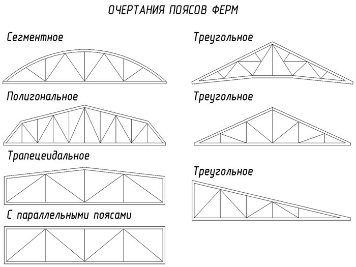
The next important parameter is the angle of inclination. Depending on it, metal trusses from profile pipes are divided into three main groups. The first group includes metal structures with an angle of inclination of 22-30 degrees. In this case, the length and height of the product are represented by a ratio of 1:5. Among the advantages of such a metal structure, one can single out a slight weight. Most often, metal triangular trusses are created this way.
In this case, it may be necessary to use braces mounted from top to bottom if the span height exceeds 14 meters. A panel 150-250 cm long will be located in the upper belt. As a result, a design with two belts and an even number of panels will be obtained. Provided that the span is more than 20 meters, the under-rafter metal structure should be mounted, linking it with support columns.
The second group includes farms from square pipes or from professional pipes and other varieties, if the angle of inclination is 15-22 degrees. The ratio of height and length between themselves reaches 1:7. The maximum frame length should not exceed 20 meters. If it is necessary to increase the height, additional procedures are required, for example, a broken belt is created.
The third group includes metal structures with an inclination angle of less than 15 degrees. In these projects, a trapezoid truss system is used. They have additional short racks. This allows you to increase the resistance to longitudinal deflection. If a shed roof is mounted, the angle of inclination of which reaches 6-10 degrees, it is necessary to consider an asymmetric shape. The division of the span may vary depending on the design features, and can be up to seven, eight or nine parts.
Separately, the Polonso farm, mounted by hand, is singled out. It is represented by two triangular trusses, which are connected by a puff. This eliminates the installation of long braces, which would have to be located in the middle panels. As a result, the weight of the structure will be optimal. 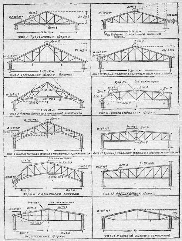
How to correctly calculate the canopy?
The calculation and manufacture of trusses from a profile pipe should be based on the basic requirements that are prescribed in SNiP. When calculating, it is important to draw up a drawing of the product, without which subsequent installation will be impossible. Initially, a diagram should be prepared, which will indicate the main dependencies between the roof slope and the length of the structure as a whole. In particular, the following should be taken into account:
It should be remembered that increasing the height with your own hands will lead to an increase bearing capacity. In this case, the snow cover will not be held on the roof. To further strengthen the metal structure, you will have to mount stiffeners. To determine the dimensions of the farm, you should be guided by the following data:
- structures up to 4.5 meters wide are mounted from parts with dimensions of 40x20x2 mm;
- products with a width of 5.5 meters are created from components measuring 40x40x2 mm;
- if the width of the structure will exceed 5.5 meters, it is optimal to choose parts 40x40x3 mm or 60x30x2 mm.
Next, you need to calculate the step, for this, the distance from one to the next support of the canopy is taken into account. Often it is standard and reaches 1.7 meters. If you break this unspoken rule, the strength of the structure may be somewhat violated. After all the required parameters are calculated, it is necessary to obtain a design diagram. To do this, use the program to achieve the required strength. Most programs have similar names to the process they are running. You can choose the program "Truss Calculation", "Truss Calculation 1.0" and other similar ones. 
When calculating, be sure to take into account the cost of one ton of metal in the purchase, as well as the cost of manufacturing the metal structure itself, that is, the costs of welding, anti-corrosion treatment and installation. Now it remains to figure out how to weld a truss from a profile pipe.
In order for truss welding to be of high quality, a number of recommendations must be followed. Among them are the following:

In order for the design to turn out in accordance with the requirements, it is important to adhere to a certain algorithm of work. Initially, the site is marked. To do this, mount vertical supports and embedded parts. If necessary, metal profile pipes can be immediately placed in pits and concreted. The installation of vertical supports is verified with a plumb line, and in order to control the parallelism, they pull the cord.
A truss is a system of usually straight rods that are interconnected by nodes. This is a geometrically unchanging structure with hinged joints (considered as hinged in the first approximation, since the stiffness of the nodes does not significantly affect the operation of the structure).
Due to the fact that the rods experience only tension or compression, the truss material is used more fully than in a solid beam. This makes such a system economical in terms of material costs, but laborious to manufacture, so when designing, it must be taken into account that the feasibility of using trusses grows in direct proportion to its span.
Farms are widely used in industrial and civil construction. They are used in many construction industries: building coating, bridges, power line supports, transport overpasses, cranes, etc.
Construction device
The main elements of the trusses are the belts that make up the contour of the truss, as well as a lattice consisting of racks and braces. These elements are connected at the nodes by adjoining or nodal gussets. The distance between the supports is called the span. Truss chords usually work for longitudinal forces and bending moments (as do solid beams); the truss grating takes over mainly shear force like a wall in a beam.
According to the location of the rods, the trusses are divided into flat (if everything is in the same plane) and spatial. flat trusses are able to perceive the load only relative to their own plane. therefore, they must be fixed from their plane with the help of ties or other elements. Spatial farms are created to perceive the load in any direction, as they create a rigid spatial system.
Classification by belts and bars
For different types loads apply different kinds farms. There are many classifications of them, depending on different signs.
Consider the types according to the outline of the belt:

a - segmented; b - polygonal; c - trapezoidal; g - with a parallel arrangement of belts; d - and - triangular
The truss chords must correspond to the static load and the type of load that determines the bending moment diagram.
The outlines of the belts largely determine the economy of the farm. In terms of the amount of steel used, the segment truss is the most efficient, but it is also the most difficult to manufacture.
According to the type of truss lattice system, there are:

a - triangular; b - triangular with additional racks; c - diagonal with ascending braces; g - diagonal with descending braces; d - trussed; e - cross;
g - cross; h - rhombic; and - semi-diagonal
Features of the calculation and design of tubular trusses
For production uses steel, 1.5 - 5 mm thick. The profile can be round or square.

The tubular profile for compressed rods is the most efficient in terms of steel consumption due to the favorable distribution of material relative to the center of gravity. With the same cross-sectional area, it has the largest radius of gyration compared to other types of rolled products. This makes it possible to design rods with the least flexibility and reduce steel consumption by 20%. Also significant advantage pipes are considered to be streamlined. Due to this, the wind pressure on such farms is less. Pipes are easy to clean and paint. all this makes the tubular profile advantageous for use in farms.
When designing trusses, you should try to center the elements at the nodes along the axes. This is done to avoid additional stress. Nodal interfaces of pipe trusses must provide a tight connection (it is necessary to prevent the occurrence of corrosion in the internal cavity of the truss).
The most rational for tubular trusses are non-shaped units with the lattice rods adjoining directly to the belts. Such nodes are performed using a special curly cutting of the ends, which minimizes the cost of labor and material. The rods are centered along the geometric axes. In the absence of a mechanism for such cutting, the ends of the lattice are flattened.
Such nodes are not permissible for all types of steel (only low-carbon or other with high ductility). If the pipes of the lattice and belts are of the same diameter, then it is advisable to connect them on the ring.
Calculation of roof trusses depending on the angle of the roof

Construction at a roof slope angle of 22-30 degrees
The angle of inclination of the roof is considered optimal for gable roof 20-45 degrees, for a lean-to 20-30 degrees.
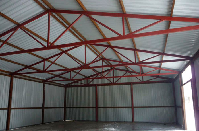
The structure of building coverings usually consists of truss trusses placed next to each other. If they are interconnected only by runs, then the system is formed variable and may lose stability.
To ensure the invariability of the structure, the designers provide for several spatial blocks from adjacent trusses, which are fastened together with ties in the planes of the chords and vertical cross ties. Other trusses are attached to such rigid blocks using horizontal elements, which ensures the stability of the structure.
To calculate the coverage of the building, it is necessary to determine the angle of inclination of the roof. This setting depends on several factors:
- view truss system
- roofing cake
- crate
- roofing material
If the angle of inclination is significant, then I use triangular-type trusses. But they have some drawbacks. This is a complex support assembly that requires articulation, which makes the entire structure less rigid in the transverse direction.
Collection of loads
Typically, the load acting on the structure is applied at the nodes to which the elements of the transverse structures are attached (for example, a suspended ceiling or roof purlins). For each type of load, it is desirable to determine the forces in the bars separately. Types of loads for roof trusses:
- constant (own weight of the structure and the entire supported system);
- temporary (load from suspended equipment, payload);
- short-term (atmospheric, including snow and wind);
To determine the permanent design load, you must first find the cargo area from which it will be collected.
The formula for determining the load on the roof:
F = (g + g1/cos a)*b ,
where g is the own mass of the truss and its connections, horizontal projection, g1 is the mass of the roof, a is the angle of inclination of the upper chord relative to the horizon, b is the distance between the trusses
Based on this formula, the greater the angle of inclination, the less the load acting on the roof. However, it should be borne in mind that an increase in the angle entails a significant increase in price due to an increase in the volume of building materials.
Also, when designing a roof, the region of construction is taken into account.. If a significant wind load is expected, then the angle of inclination is laid to a minimum and the roof is made single-pitched.
Snow is a temporary load and loads the farm only partially. Loading half a truss can be very disadvantageous for medium sized rasks.
The total snow load on the roof is calculated by the formula:
Sp is the calculated value of snow weight per 1 m2 of horizontal surface;
μ - calculation coefficient, to take into account the slope of the roof (according to SNiP, it is equal to one if the angle of inclination is less than 25 degrees and 0.7 if the angle is from 25 to 60 degrees)
Wind pressure is considered significant only for vertical surfaces and surfaces if their angle of inclination to the horizon is greater than 30 degrees (relevant for masts, towers and steep roof trusses). The wind load, like the rest, is reduced to nodal.
Effort Definition
When designing tubular roof trusses, one should take into account their increased bending rigidity and the significant influence of the rigidity of the joints at the nodes. Therefore, for tubular profiles, the calculation of trusses according to the hinged scheme is allowed with a ratio of sectional height to length of not more than 1/10 for structures that will be operated at a design temperature below -40 degrees.
In other cases, it is necessary to calculate the bending moments in the rods due to the stiffness of the nodes. In this case, axial forces can be calculated according to the hinged scheme, and additional moments can be found approximately.

Instructions for calculating the roof truss
- the design load is determined (using SNiP "Loads and Impacts")
- there are efforts in the truss rods (you should decide on the design scheme)
- the calculated length of the rod is calculated (equals the product of the length reduction factor (0.8) by the distance between the centers of the nodes)
- testing of compressed rods for flexibility
- having asked for the flexibility of the rods, select the section according to the area
When pre-selecting for belts, the value of flexibility is taken from 60 to 80, for the lattice 100-120.
Summing up
With proper design of the truss system, you can significantly reduce the amount of material used and make the construction of the roof much cheaper. For the correct calculation, it is necessary to know the region of construction, to determine the type of profile, based on the purpose and type of object. Applying the right technique to find the calculated data, it is possible to achieve the optimal ratio between the price of erecting a structure and its operational characteristics.
The design of metal structures is one of the most important areas of construction activity. To determine the required profile parameters, expensive licensed software is used, which requires specialized education and skills in working with a specific software package.
At the same time, there are situations when you need to make a drawing “on the knee”, select the right rolled product, calculate the weight of the beam to determine the cost and order the metal. In cases where it is not possible to use special programs, free online and desktop programs can become convenient assistants in the calculation of metal structures:
- metal-roll calculator Arsenal;
- online calculator Metalcalc;
- online program sopromat.org for calculation of beams and trusses;
- calculation of beams in Sopromatguru online;
- desktop-program "Farm".
1. Arsenal rolled metal calculator
The Arsenal company provides everyone with the opportunity to save their time by using the proprietary desktop program for calculating the theoretical weight of a metal profile of any kind, including ferrous and stainless, as well as non-ferrous metal. The site is available and online version of the program .
In order to calculate the profile, you need to enter information about the thickness of the metal, the length of the segment, height and width. You can also select a brand of rolled profile from the assortment and set the required length. In this case, the program will determine it dimensions and weight automatically.
2. Metalcalc online calculator
Online calculator metalcalc- a convenient resource for determining the weight and length of rolled metal. When setting the main technical parameters of the product (range number or overall dimensions of the profile, its length), the program will determine its weight. Calculations are performed on the basis of current GOSTs and are characterized by maximum accuracy.
The program also has a recalculation function. If you specify the weight and size of the profile, the service will calculate its length. The resource is absolutely free and easy to use.
3. Free online program sopromat.org for calculating beams and trusses
Online sopromat.org presented free online program for the calculation of beams and trusses by the finite element method. The calculation can be performed, among other things, for statically indeterminate frames.
The service can be useful both for students to perform term papers, and practicing engineers to determine the parameters of real metal structures. The online resource allows you to:
- determine displacements in nodes;
- calculate the reactions of the supports;
- plot Q, M, N
- save the results of calculations and the scheme of loads;
- export results to DXF drawing format.
The site always contains the latest version of the program. There is a version Mini for download and work on mobile devices. The mobile program has all the advantages of the full version.
4. Calculation of beams in Sopromatguru
In the near future, the authors plan to add a truss calculation function to the program. Today, the online resource allows you to set the parameters of a beam, support, load for free and get a diagram. For access to a detailed calculation, the authors of the program ask you to transfer a symbolic payment. It is worth noting that the online service is beautifully designed and equipped with a clear interface.
5. Free desktop-program "Farm"
small program Farm allows you to calculate a flat statically determinate truss and save the results. To get started, you must specify the geometric parameters of the truss (bar dimensions, heights, braces positions, loads).
The calculation is performed by the method of cutting nodes. The forces in the truss rods are determined, as well as the reactions of the supports. The maximum number of truss panels is 16, the number of loads is no more than 20. The software package can also be used to calculate statically indeterminate trusses.
Determination of the internal forces of the truss
Often we do not have the opportunity to use a conventional beam for a particular structure, and we are forced to use a more complex structure called a truss.
although it differs from the calculation of the beam, it will not be difficult for us to calculate it. You will only need attention, basic knowledge of algebra and geometry, and an hour or two of free time.
So, let's begin. Before calculating the farm, let's ask ourselves some real situation that you might encounter. For example, you need to block a garage 6 meters wide and 9 meters long, but you don’t have floor slabs or beams. Only metal corners of various profiles. Here we will collect our farm from them!
Subsequently, girders and corrugated board will be based on the farm. The support of the truss on the walls of the garage is articulated.
To begin with, you will need to find out all the geometric dimensions and angles of your farm. Here we need our mathematics, namely geometry. We find the angles using the cosine theorem.
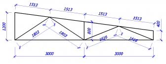

Then you need to collect all the loads on your farm (you can see in the article). Let's say you have the following loading option:
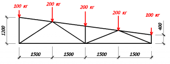
Next, we need to number all the elements, nodes of the farm and set the support reactions (the elements are signed in green, and the nodes in blue).
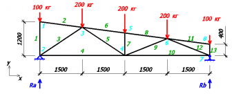
To find our reactions, we write the equations for the balance of forces on the y axis and the equation for the balance of moments with respect to node 2.
Ra+Rb-100-200-200-200-100=0;
200*1.5 +200*3+200*4.5+100*6-Rb*6=0;
From the second equation, we find the support reaction Rb:
Rb=(200*1.5 +200*3+200*4.5+100*6) / 6;
Rb=400 kg
Knowing that Rb=400 kg, from the 1st equation we find Ra:
Ra=100+200+200+200+100-Rb;
Ra=800-400=400 kg;
Once the support reactions are known, we must find the node with the fewest unknowns (each numbered element is an unknown). From this point on, we begin to divide the truss into separate nodes and find the internal forces of the truss rods in each of these nodes. It is on these internal forces that we will select the sections of our rods.
If it turned out that the forces in the rod are directed from the center, then our rod tends to stretch (return to its original position), which means that it is compressed. And if the efforts of the rod are directed towards the center, then the rod tends to shrink, that is, it is stretched.
So, let's move on to the calculation. There are only 2 unknown quantities in node 1, so let's consider this node (we set the directions of efforts S1 and S2 from our own considerations, in any case, we will get it right in the end).
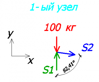
Consider the equilibrium equations on the x and y axes.
S2 * sin82.41 = 0; - on the x-axis
-100 + S1 = 0; - on the y-axis
It can be seen from the 1st equation that S2=0, that is, the 2nd rod is not loaded!
It can be seen from the 2nd equation that S1=100 kg.
Since the value of S1 turned out to be positive, it means that we have chosen the direction of effort correctly! If it would turn out to be negative, then the direction should be changed and the sign should be changed to “+”.
Knowing the direction of the effort S1, we can imagine what the 1st rod is like.
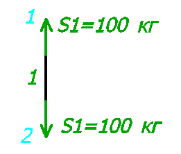
Since one force was directed to the node (node 1), the second force will also be directed to the node (node 2). So our rod is trying to stretch, which means it is compressed.
Next, consider node 2. There were 3 unknowns in it, but since we have already found the value and direction of S1, only 2 unknowns remain.

Yet again
100 + 400 - sin33.69 * S3 = 0 - on the y-axis
- S3 * cos33.69 + S4 = 0 - on the x-axis
From the 1st equation S3 = 540.83 kg (rod #3 is compressed).
From the 2nd equation S4 = 450 kg (rod #4 is stretched).
Consider the 8th node:

Let's write equations on the x and y axes:
100 + S13 = 0 - on the y-axis
-S11 * cos7.59 = 0 - on the x-axis
From here:
S13 = 100 kg (rod #13 compressed)
S11 = 0 (zero rod, there is no effort in it)
Consider the 7th node:

Let's write equations on the x and y axes:
100 + 400 - S12 * sin21.8 = 0 - on the y-axis
S12 * cos21.8 - S10 = 0 - on the x-axis
FROM the 1st equation we find S12:
S12 = 807.82 kg (rod #12 compressed)
From the 2nd equation we find S10:
S10 = 750.05 kg (rod #10 stretched)
Let's take a look at node #3. As far as we remember, the 2nd rod is zero, which means we will not draw it.

Equations on the x and y axes:
200 + 540.83 * sin33.69 - S5 * cos56.31 + S6 * sin7.59 = 0 - to the y-axis
540.83 * cos33.69 - S6 * cos7.59 + S5 * sin56.31 = 0 - on the x-axis
And here we already need algebra. I will not describe in detail the methodology for finding unknown quantities, but the essence is this - from the 1st equation we express S5 and substitute it into the 2nd equation.
As a result, we get:
S5 = 360.56 kg (rod #5 stretched)
S6 = 756.64 kg (rod #6 compressed)
Consider node #6:
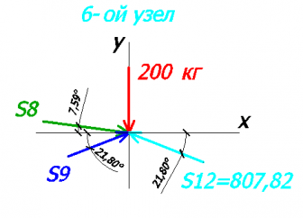
Let's write equations on the x and y axes:
200 - S8 * sin7.59 + S9 * sin21.8 + 807.82 * sin21.8 = 0 - on the y-axis
S8 * cos7.59 + S9 * cos21.8 - 807.82 * cos21.8 = 0 - on the x-axis
Just as in the 3rd node, we find our unknowns.
S8 = 756.64 kg (rod #8 compressed)
S9 = 0 kg (rod #9 zero)
Consider node #5:

Let's make equations:
200 + S7 - 756.64 * sin7.59 + 756.64 * sin7.59 = 0 - on the y-axis
756.64 * cos7.59 - 756.64 * cos7.59 = 0 - on the x-axis
From the 1st equation we find S7:
S7 = 200 kg (rod #7 compressed)
As a test of our calculations, consider the 4th node (there are no forces in the rod No. 9):

Let's write equations on the x and y axes:
200 + 360.56 * sin33.69 = 0 - on the y-axis
-360.56 * cos33.69 - 450 + 750.05 = 0 - on the x-axis
In the 1st equation it turns out:
In the 2nd equation:
This error is acceptable and is most likely due to the angles (2 decimal places instead of 3).
As a result, we get the following values:

I decided to double-check all our calculations in the program and got exactly the same values:

Selection of the section of the truss elements
At metal truss calculation after all the internal forces in the rods are found, we can proceed to the selection of the section of our rods.
For convenience, we summarize all the values in a table.