How to dismantle smd components. About dismantling SMD components from printed circuit boards
This article will consider one of the working ways to unsolder smd components. At what the desoldering will take place in a not quite standard way, but despite this, it is very effective. The heating of the elements takes place evenly, without the danger of overheating, since the temperature can be regulated!
Increasingly, SMD parts are used in production, as well as among radio amateurs. It is more convenient to work with them, since it is not necessary to drill holes for the leads, and the devices are very miniature.
SMD components are quite reusable and reusable. Here again, the obvious superiority of surface mounting appears, because it is much easier to solder small parts. They are very easy to blow off with a special soldering dryer from the board. But if you don’t have this at hand, then an ordinary household iron will help you out.
Dismantling of SMD parts
So, my LED lamp burned out, and I will not fix it. I will unsolder it into parts for my future homemade products.

We disassemble the light bulb, remove the top cap.

We take out the board from the base of the base.


We solder hinged components and parts, wires. In general, there should be a board with only SMD parts.


We fix the iron upside down. This must be done firmly so that it does not tip over during the soldering process.
The use of an iron is also good because it has a regulator that will quite accurately maintain the set temperature of the sole surface. This is a huge plus, since surface components are very afraid of overheating.
We set the temperature to about 180 degrees Celsius. This is the second ironing mode, if my memory serves me right. If soldering does not work, gradually increase the temperature.
We put the board from the light bulb on the sole of the inverted iron.

We wait 15-20 seconds until the board warms up. At this time, we wet each detail with flux. The flux will not overheat, it will be a kind of assistant when desoldering. With it, all elements are removed without difficulty.

Once everything is well warmed up, all the parts can be brushed off the board by hitting the board on some surface. But I'll do it carefully. To do this, take a wooden stick to hold the board in place and use tweezers to disconnect each component of the board.
Naked board at the end of work:

Soldered details:


This method will allow you to solder any boards with SMD parts very quickly. Arm your friends!
When any equipment breaks down, it is not at all necessary to immediately throw it in the trash. If you are fond of electronics and radio engineering, it would be wiser to solder the working elements of the microcircuit. Suddenly, in the future you will need a capacitor, transistor or resistor if you decide to do it. In this article, we will tell you how to unsolder the radio components from the board so as not to damage anything.
What is needed for this?
There are many devices for soldering parts. Of course, a radio amateur cannot do without a soldering iron, which will be the main assistant in this matter. However, in addition to the soldering iron, in order to desolder the element, you will need:
You also need to prepare the workplace. It must be well lit. It is best if the lamp is above the workplace so that the light falls vertically without creating shadows.
Dismantling techniques
So, first we will talk about the most popular technology - how to solder a part from a board with a soldering iron without additional tools. After that, we briefly consider simpler methods.
If you want to solder an electrolytic capacitor, it is enough to grab it with tweezers (or a crocodile), warm up 2 terminals and quickly but carefully remove them from the board.

The same is true with transistors. We drip solder on all 3 outputs and remove the radio component from the board. 
As for resistors, diodes and non-polar capacitors, very often their legs are bent during soldering from the back of the board, which makes it difficult to solder without additional tools. In this case, it is recommended to first warm up one terminal and, with the help of a crocodile, with a little effort, pull out part of the part from the circuit (the leg should unbend). Then we perform a similar procedure with the second conclusion.
We have considered the technique when there is nothing at hand except a soldering iron. But if you purchased a set of needles, then it will be even easier to unsolder the element: first, heat up the contact with a soldering iron, and then put the needle on the output suitable diameter(it must pass through the hole in the chip) and wait until the solder cools down. After that, we take out the needle and get a bare conclusion, which can be easily removed. If there are several legs at the radio component, we also act - we warm up the contact, put on the needles, wait and remove.
Everything that we talked about in this article, you can clearly see in the video, which provides the technology for desoldering elements from the board:
By the way, instead of special needles, you can even use ordinary ones that come with a syringe. However, in this case, you first need to grind off the end of the needle so that it is at a right angle.
Soldering the part with a dismantling braid is also not difficult. Before starting work, wet the end of the winding with alcohol-rosin flux. After that, apply a braid in the place of soldering (on the solder) and heat it with a soldering iron tip. As a result, the heated solder should be absorbed into the braid, which will allow the leads of the radio components to be released.
With a desoldering pump, things are similar - the spring is cocked, the contact is heated, after which the tip is brought to the molten solder and the button is pressed. A vacuum is created, which draws the solder into the desoldering pump.
That's all I wanted to tell you about how to solder radio components from the board at home. We hope that the methods and video tutorials provided were useful and interesting for you. Finally, I would like to note that it is possible to solder the elements from the microcircuit with a building hair dryer, but we do not recommend doing this. The hair dryer can damage nearby parts, as well as the one you want to remove!
Interesting
Many people wonder how to solder SMD components correctly. But before dealing with this problem, it is necessary to clarify what these elements are. Surface Mounted Devices - translated from English, this expression means surface mount components. Their main advantage is a greater mounting density than conventional parts. This aspect affects the use of SMD elements in the mass production of printed circuit boards, as well as their cost-effectiveness and manufacturability of installation. Ordinary parts with wire-type leads have lost their wide application along with the rapidly growing popularity of SMD components.
Errors and the basic principle of soldering
Some craftsmen claim that soldering such elements with their own hands is very difficult and rather inconvenient. In fact, similar work with HP components is much more difficult to carry out. In general, these two types of parts are used in various areas of electronics. However, many people make certain mistakes when soldering SMD components at home.
SMD components
The main problem that amateurs face is the choice of a thin tip for a soldering iron. This is due to the existence of the opinion that when soldering with an ordinary soldering iron, you can smear the legs of SMD contacts with tin. As a result, the soldering process is long and painful. Such a judgment cannot be considered correct, since the capillary effect, surface tension, and wetting force play an important role in these processes. Ignoring these additional tricks makes it difficult to do the job yourself.
 Soldering SMD components
 In order to properly solder SMD components, certain steps must be followed. To begin with, apply the soldering iron tip to the legs of the element taken. As a result, the temperature begins to rise and the tin melts, which eventually completely flows around the leg of this component. This process is called wetting force. At the same instant, the tin flows under the leg, which is explained by the capillary effect. Together with wetting the legs, a similar action occurs on the board itself. The result is a uniformly filled bundle of boards with legs.
Solder contact with neighboring legs does not occur due to the fact that a tension force begins to act, forming individual tin drops. It is obvious that the described processes proceed on their own, with only a small participation of the solderer, who only warms up the legs of the part with a soldering iron. When working with very small elements, they may stick to the tip of the soldering iron. To prevent this from happening, both sides are soldered separately.
Soldering in the factory
This process takes place on the basis of the group method. Soldering SMD components is carried out using a special solder paste, which is evenly distributed in a thin layer on the prepared printed circuit board, where there are already contact pads. This method of application is called screen printing. The material used in its appearance and consistency resembles toothpaste. This powder consists of solder to which flux has been added and mixed. The application process is carried out automatically as the printed circuit board passes through the conveyor.
 Factory soldering of SMD parts
 Further, the robots installed along the movement tape lay out all the necessary elements in the right order. Parts in the process of moving the board are firmly held in place due to the sufficient stickiness of the solder paste. The next step is heating the structure in a special furnace to a temperature that is slightly higher than that at which the solder melts. As a result of this heating, the solder melts and flows around the legs of the components, and the flux evaporates. This process makes the parts soldered into place. After the stove, the board is allowed to cool, and everything is ready.
Necessary materials and tools
In order to do the soldering of SMD components with your own hands, you will need certain tools and Supplies, which include the following:
- soldering iron for soldering SMD contacts;
- tweezers and side cutters;
- an awl or needle with a sharp end;
- solder;
- a magnifying glass or magnifying glass, which are necessary when working with very small details;
- neutral liquid flux no-clean type;
- a syringe with which you can apply the flux;
- in the absence of the latter material, an alcohol solution of rosin can be dispensed with;
- for the convenience of soldering, the masters use a special soldering dryer.
 Tweezers for installing and removing SMD components
 The use of flux is essential and must be liquid. In this state, this material degreases the working surface, and also removes the oxides formed on the soldered metal. As a result, an optimal wetting force appears on the solder, and the soldering drop retains its shape better, which facilitates the entire process and eliminates the formation of "snot". Usage alcohol solution rosin will not allow to achieve a significant result, and the resulting white coating unlikely to be removed.

The choice of soldering iron is very important. The best tool is one that can be adjusted in temperature. This allows you not to worry about the possibility of damage to parts by overheating, but this nuance does not apply to the moments when you need to desolder SMD components. Any soldered part is able to withstand temperatures of about 250-300 ° C, which provides an adjustable soldering iron. In the absence of such a device, you can use a similar tool with a power of 20 to 30 W, designed for a voltage of 12-36 V.
Using a 220 V soldering iron will not lead to the best results. It's connected with high temperature heating its tip, under the influence of which the liquid flux quickly evaporates and does not allow the parts to be effectively wetted with solder.
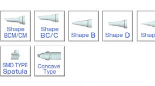
Experts do not advise using a soldering iron with a conical tip, since the solder is difficult to apply to parts and a lot of time is wasted. The most effective is considered a sting called "Microwave". Its obvious advantage is a small hole in the cut for a more convenient grip of the solder in the right amount. Even with such a sting on a soldering iron, it is convenient to collect excess soldering.

You can use any solder, but it is better to use a thin wire, with which it is comfortable to dose the amount of material used. The soldered part with the help of such a wire will be better processed due to more convenient access to it.
How to solder SMD components?
Work order
The process of soldering, with a careful approach to theory and gaining some experience, is not difficult. So, the whole procedure can be divided into several points:
- It is necessary to place SMD components on special pads located on the board.
- A liquid flux is applied to the legs of the part and the component is heated with a soldering iron tip.
- Under the action of temperature, the contact pads and the legs of the part are flooded.
- After pouring, the soldering iron is removed and time is given for the component to cool. When the solder has cooled, the job is done.
 The process of soldering SMD components
 When performing similar actions with a microcircuit, the soldering process is slightly different from the above. The technology will look like this:
- The feet of the SMD components fit exactly into their contact points.
- In places of contact pads, wetting with flux is performed.
- To accurately hit the part on the seat, you must first solder one of its extreme legs, after which the component is easily exposed.
- Further soldering is carried out with the utmost care, and the solder is applied to all legs. Excess solder is removed with a soldering iron tip.

How to solder with a hair dryer?
With this method of soldering, it is necessary to lubricate the seats with a special paste. Then the necessary part is placed on the contact pad - in addition to components, these can be resistors, transistors, capacitors, etc. For convenience, you can use tweezers. After that, the part is heated with hot air supplied from a hair dryer at a temperature of about 250º C. As in the previous soldering examples, the flux evaporates under the action of temperature and melts the solder, thereby flooding the contact tracks and legs of the parts. Then the hair dryer is removed, and the board begins to cool. When completely cooled, the soldering can be considered finished.

Everyone understands how it is possible with the help of a conventional soldering iron EPSN, with a power of 40 watts, and a multimeter, various electronic equipment, with output parts. But such details are now found, mainly only in power supplies of various equipment, and similar power boards, where significant currents flow, and there is high voltage, and all control boards now go to the SMD element base.
On board SMD radio components
So what if we don’t know how to dismantle and solder back, because then at least 70% of the possible repairs of equipment, we will not be able to do it on our own ... Someone who is not very deeply familiar with the topic of installation and dismantling may say, for this requires a soldering station and a soldering dryer, various nozzles and tips for them, no-clean flux, such as RMA-223, and the like, which is in the workshop home master usually doesn't happen.

Soldering Station
I have a soldering station and a hair dryer, nozzles and tips, fluxes, and solder with flux various diameters. But what if you suddenly need to fix the equipment, on the road to order, or visiting friends? But is it inconvenient to disassemble and bring a defective board home, or to a workshop where appropriate soldering equipment is available, for one reason or another? It turns out there is a way out, and quite simple. What do we need for this?
What you need for good soldering
- 1. Soldering iron EPSN 25 watts, with a tip sharpened into a needle, for mounting a new microcircuit.

- 2. Soldering iron EPSN 40-65 watts with a tip sharpened under a sharp cone, for dismantling a microcircuit, using Rose or Wood alloy. A soldering iron with a power of 40-65 watts must be turned on necessarily through a Dimmer, a device for adjusting the power of the soldering iron. It is possible such as in the photo below, very convenient.

- 3. Alloy Rose or Wood. We bite off a piece of solder with side cutters from a droplet, and put it directly on the contacts of the microcircuit on both sides, if we have it, for example, in the Soic-8 package.


- 4. Dismantling braid. It is required in order to remove solder residues from the contacts on the board, as well as on the microcircuit itself, after dismantling.

- 5. SCF flux (alcohol rosin flux, crushed into powder, dissolved in 97% alcohol, rosin), or RMA-223, or similar fluxes, preferably based on rosin.

- 6. Flux Off, or 646 thinner, and a small, medium bristle brush, usually used in school, for painting in art classes.

- 7. Tubular solder with flux, with a diameter of 0.5 mm, (preferably, but not necessarily this diameter).

- 8. Tweezers, preferably curved, L-shaped.

Unsoldering planar parts
So how does the process itself take place? Something . We bite off small pieces of solder (alloy) Rose or Wood. We apply our flux, abundantly, to all contacts of the microcircuit. We put a drop of solder to Rose, on both sides of the microcircuit, where the contacts are located. We turn on the soldering iron, and set it with a dimmer, the power is approximately 30-35 watts, I don’t recommend it anymore, there is a risk of overheating the microcircuit during dismantling. We carry out the sting of a heated soldering iron, along all the legs of the microcircuit, on both sides.

At the same time, the contacts of the microcircuit will close with us, but this is not scary, after we dismantle the microcircuit, we can easily remove excess solder from the contacts on the board and from the contacts on the microcircuit with the help of a dismantling braid.
So, we took up our chip with tweezers, along the edges, where there are no legs. Usually the length of the microcircuit, where we hold it with tweezers, allows you to simultaneously drive the soldering iron tip, between the tips of the tweezers, alternately from both sides of the microcircuit, where the contacts are located, and slightly pull it up with tweezers. Due to the fact that during the melting of the Rose or Wood alloy, which have a very low melting point (about 100 degrees), relative to the lead-free solder, and even the usual POS-61, and moving with the solder on the contacts, it thereby reduces the overall melting point of the solder .

Dismantling chips using a braid
And in this way, the microcircuit is dismantled with us, without overheating dangerous for it. On the board, we have solder residues, Rose alloy and lead-free, in the form of sticky contacts. To bring the board back to normal, we take a dismantling braid, if the flux is liquid, you can even dip its tip into it, and put it on the solder “snot” formed on the board. Then we warm up from above, pressing down with a soldering iron tip, and draw a braid along the contacts.

Soldering braided radio components
Thus, all the solder from the contacts is absorbed into the braid, passes to it, and the contacts on the board are completely cleaned of solder. Then the same procedure must be done with all the contacts of the microcircuit, if we are going to solder the microcircuit to another board, or to the same one, for example, after flashing with a programmer, if it is a Flash memory chip containing the BIOS firmware of the motherboard, or monitor, or which or other technology. This procedure must be performed to clean the contacts of the microcircuit from excess solder. After that, we apply the flux again, put the microcircuit on the board, position it so that the contacts on the board strictly correspond to the contacts of the microcircuit, and there is still some space left on the contacts on the board, along the edges of the legs. Why are we leaving this place? So that you can lightly touch the contacts, with a soldering iron tip, solder them to the board. Then we take a 25 watt EPSN soldering iron, or a similar low-power one, and touch the two legs of the microcircuit located diagonally.

As a result, the microcircuit turns out to be “stuck” with us, and will no longer budge, since the melted solder on the contact pads will hold the microcircuit. Then we take solder with a diameter of 0.5 mm, with a flux inside, bring it to each contact of the microcircuit, and simultaneously touch the tip of the soldering iron, solder, and each contact of the microcircuit. I do not recommend using solder of a larger diameter, there is a risk of hanging “snot”. Thus, we have solder “deposited” on each contact. We repeat this procedure with all contacts, and the microcircuit is soldered into place. With experience, all these procedures can really be completed in 15-20 minutes, or even in less time. We only need to wash off the flux residues from the board, using solvent 646, or Flux Off cleaning agent, and the board is ready for tests after drying, and this happens very quickly, since the substances used for washing are very volatile. 646 solvent, in particular, is based on acetone. The inscriptions, silk-screen printing on the board, and the solder mask are not washed off or dissolved.

The only thing is that it will be problematic to dismantle a microcircuit in a Soic-16 package and more multi-output in this way, due to the difficulties with simultaneous heating, a large number of legs. Good soldering everyone, and less overheated microcircuits! Specially for Radio circuits - AKV.
Discuss the article SOLDERING SMD PARTS WITHOUT A HAIRDRYER
One trouble happened here the other day - I burned the power track on the UART-USB converter board (on ATtiny2313). I had to replace the burnt track with a jumper wire. Everything seems to be working as it should, but this posting began to annoy me. I decided to upgrade the converter board for this case, so to speak, upgrade to version No. 2. And since the microcontroller is intact, it can be unsoldered and rearranged to a new board. Since I promised to show how to solder them, then, at the same time, I will fulfill my promise.
Desoldering SMD components.
Of course, for desoldering SMD components the best tool is a hair dryer, but in the absence of a hair dryer, you have to get out with improvised means. There are many ways, from making special nozzles on a soldering iron (to heat all the legs at the same time), the use of mica, chemical etching and ending with exotic methods, such as heating the board with a powerful spotlight placed close to it. For the most part, these methods are not particularly humane to the board and tracks. They shamelessly overheat and become ill-suited for reuse.
For myself, I chose a method that is as gentle as possible both for the board and tracks, and for soldered components. In addition, this method does not require any special materials or technologies.
Materials tools:
1
Special "braid" for solder removal. Getting it is not a problem - it is not a shortage. Can be replaced with a bundle of thin wires (of course, not oxidized);
2
Liquid flux. I buy a flux called F5. Can be replaced with alcohol-rosin, but the effect will be worse;
3
Needle or thin awl, tweezers.
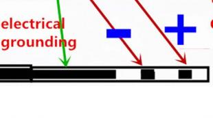
The desoldering technology is as follows:
1
We moisten abundantly with flux, both the soldered legs and the “braid” itself;
2
With the help of a “braid” and a soldering iron, we remove the solder as much as possible. This will require several passes. Don't skimp on the braid!
3
After the solder is removed as much as possible, we proceed to tear off the legs from the tracks. This is done in the following way: wielding the needle as a lever, slightly pry the leg, leaning on the next one. Great effort is not needed - the legs lag behind very easily with a characteristic click. We do this procedure with all legs. If any leg does not lend itself - we do not force it, we leave it as it is;
4
After all the legs are torn off, the microcircuit will no longer hold anything - just pick it up from the board. If several legs have not come off the tracks, it’s okay to grab the case with tweezers (or pry it with an awl) and carefully tear it off with a little effort.
(Visited 10 034 times, 3 visits today)
Section: Tags: ,Post navigation
054-Unsoldering SMD components.: 29 comments
- hryam
Of course, it is much easier to solder with a hairdryer, if there are additional nozzles, then in general a song. You play - you shoot. Your method is slightly vandal, it is quite possible to tear off the track under it along with the leg of the microcircuit, it’s good if you only need a microcircuit, but what if it’s the other way around? ...
- GetChiper Post author
In this I agree. But this is a less vandalistic way than, for example, pouring rosin or heating it with a kilowatt spotlight or an industrial hair dryer.
We must understand that this method is only suitable for single desoldering if this happens to you often - a blow dryer is a must! - SemLeik
And also, are SMD elements found only on computer boards ??
- GetChiper Post author
Why only on computer boards? They are used very widely. It is more profitable for manufacturers to make electronic equipment on SMD components for the following reasons:
- SMD are cheaper
- under SMD, you do not need to drill holes in the boards (this greatly simplifies and reduces the cost of production)
- SMD take up less space and are stored in tapes convenient for automatic mounting
- SMD is easier to mount automaticallyFor the same reasons, except for the last point, for radio amateurs, it is also more profitable to use SMD components.
- cosmogon
Greetings. What hair dryer do you recommend? What brand, type. Not only soldering, but also soldering. Fan in the handle, in the block? What is better than one or the other? What is the price, and within what range?
- GetChiper Post author
I won’t say anything on the hair dryer’s bill - I don’t have it myself. I use a soldering iron.
- anatoliy
Fan rulez!!
And even cooler technological convection oven 😀
It's just no words, just emotions! Moreover, positive
I tried to unsolder the motherboard somehow for the sake of fun. I put the thermostat on 290, it warmed up and beeped. He quickly took out the board and right in the frame about the edge of the open cardboard box. Bang!! All the details are there 🙂
And soldering is just a fairy tale. Smeared with paste. put the details. shoved the fee. Selected a profile. Enabled. 30 sec. Biknulo took out. cooled, washed ready. All parts are strictly in the center of the sites. all at the same height.
With a certain skill, you can assemble it from a household electric oven 🙂 - aui2002
Rumor has it that instead of an oven, you can take some powerful halogen spotlights. Nothing is fried either.
- anatoliy
It turns out ik. Still need to control the temperature. Our men made from a household oven. Microcontroller 4 thermocouples. And how is it??? Well, the IR sensor is from the motion detector.
Differences from the industrial did not notice. Except for the price! - GetChiper Post author
Wow - this is industrial technology! Although I already see the advantages of the stove (even for small boards).
- aui2002
Well, then it’s easier to buy a cheap autoclave stove (used in chemical laboratories) a new low-temperature or old high-temperature one (high-temperature ones heat up to about 1000 Celsius, but over time they “lose their grip” and do not warm up above 400-500. They are usually written off or sold for next to nothing.)
The advantage over the oven is the small size (30x20x40cm) and the built-in heating rate control system.
- anatoliy
Logically 🙂
But it's not available everywhere! I would get one like this. Apply a conductive coating to the glass. It just needs 400C.Moreover, when soldering, it is not the speed that matters, but the so-called temperature profile. which must be strictly adhered to.
Another important detail is the frame. In which the fee is fixed. It should be possible to remove it from the oven both in a cold state and in a hot one. Moreover, no shocks. Otherwise, the details will crumble. - aui2002
In them, as a rule, there are 1-2 pairs of guides (sled) under them, the frame is quite easy to bungle.
And as for the temperature profile, such furnaces are just “sharpened” for uniform heating of the entire volume. - anatoliy
Well, what do you need to try 🙂 As I understand it, do you have a volunteer for the experiment? A powerful trinistor MK and 4 thermocouples and you will be happy 🙂 You can also organize blowing through the intake air for a sharp drop in temperature. And suitability is easy to determine. Set the thermocouple to heat at maximum power up to 300 degrees, then turn it off abruptly and build a heating-cooling profile in seconds. Then compare with the recommended for soldering. There are almost any datasheet on SMD parts. And realize suitability for alteration.
IMHO, when soldering, it is necessary to heat up relatively sharply and cool it down smoothly - ZagZag
Here I was looking for information about the definition of SMD components.
Well, with resistors, everything is clear. 3 digits: 2 - face value, last - degree.
Examples:
102 = 10 * 10^2 = 1000 ohm = 1 ohm
103 = 10 * 10^3 = 10 com
Topic article.