Thin-walled shells and thick-walled cylinders. Thin-walled shells and thick-walled cylinders A thin-walled vessel consisting of two cylinders with diameters
Purpose: to form an idea about the features of deformation and strength calculation of thin-walled shells and thick-walled cylinders.
Calculation of thin-walled shells
Shell - This is a structural element limited by surfaces located at a close distance from each other. A shell is called thin-walled if it satisfies the condition p/h> 10, where h- shell thickness; R- the radius of curvature of the middle surface, which is the locus of points equally spaced from both surfaces of the shell.
The parts, the shape of which is taken by the shell, include automobile tires, vessels, internal combustion engine liners, load-bearing car bodies, aircraft fuselages, ship hulls, ceiling domes, etc.
It should be noted that in many cases shell structures are optimal, since a minimum of materials is spent on their manufacture.
A characteristic feature of most thin-walled shells is that they are bodies of revolution in shape, i.e., each of their surfaces can be formed by rotating a certain curve (profile) around a fixed axis. Such bodies of revolution are called axisymmetric. On fig. 73 shows the shell, the middle surface of which is obtained by rotating the profile sun around the axis AS.
We select from the middle surface in the vicinity of the point TO., lying on this surface, an infinitesimal element 1122 two meridional planes AST and AST 2 s angle d(p between them and two sections normal to the meridians HOt and 220 2 .
meridional called a section (or plane) passing through the axis of rotation AS. Normal called the section perpendicular to the meridian Sun.
Rice. 73.
Normal sections for the considered vessel are conical surfaces with vertices 0 and Oh g lying on the axis AS.
Let us introduce the following notation:
p t- arc curvature radius 12 in meridional section;
R,- arc curvature radius 11 in normal section.
In general p t and R, are a function of the angle in- angle between axis AC and normal 0,1 (see fig. 73).
A feature of the work of shell structures is that all its points, as a rule, are in a complex stressed state, and strength theories are used to calculate shells.
To determine the stresses arising in a thin-walled shell, the so-called momentless theory. According to this theory, it is believed that there are no bending moments among the internal forces. The shell walls work only in tension (compression), and the stresses are evenly distributed over the wall thickness.
This theory is applicable if:
- 1) the shell is a body of revolution;
- 2) shell wall thickness S is very small compared to the radii of curvature of the shell;
- 3) the load, gas or hydraulic pressure are distributed symmetrically about the axis of rotation of the shell.
The combination of these three conditions makes it possible to accept the hypothesis of the invariability of the stress across the wall thickness in a normal section. Based on this hypothesis, we conclude that the shell walls work only in tension or compression, since bending is associated with an uneven distribution of normal stresses over the wall thickness.
Let us establish the position of the main areas, i.e. those areas (planes) in which there are no tangential stresses (m = 0).
It is obvious that any meridional section divides the thin-walled shell into two parts, symmetrical both in terms of geometry and force. Since neighboring particles are deformed in the same way, there is no shift between the sections of the obtained two parts, which means that there are no shear stresses in the meridional plane (m = 0). Therefore, it is one of the main sites.
By virtue of the law of pairing, there will be no tangential stresses in sections perpendicular to the meridional section. Therefore, the normal section (platform) is also the main one.
The third main platform is perpendicular to the first two: at the outer point To(see Fig. 73) it coincides with the side surface of the shell, in it r = o = 0, thus, in the third main area o 3 = 0. Therefore, the material at the point To experiences a plane stress state.
To determine the principal stresses, we select in the vicinity of the point To infinitesimal element 1122 (see fig. 73). On the faces of the element, only normal stresses a „ and o, . The first one a t called meridional and the second a, - circumferential tension, which are the principal stresses at a given point.
Voltage vector a, directed tangentially to the circle obtained from the intersection of the median surface with a normal section. The stress vector o„ is directed tangentially to the meridian.
Let us express the principal stresses in terms of the load (internal pressure) and the geometrical parameters of the shell. For determining a t and a, two independent equations are needed. The meridional stress o„ can be determined from the condition of equilibrium of the cut-off part of the shell (Fig. 74, a):
Substituting mr t sin 9, we get
The second equation is obtained from the equilibrium condition of the shell element (Fig. 74, b). If we project all the forces acting on the element onto the normal and equate the resulting expression to zero, then we get
In view of the small angles, we take
As a result of the mathematical transformations carried out, we obtain an equation of the following form:
This equation is called Laplace equations and establishes the relationship between meridional and circumferential stresses at any point of a thin-walled shell and internal pressure.
Since the dangerous element of the thin-walled shell is in a plane stress state, based on the results obtained with t and a h and also based on the dependence 
Rice. 74. Fragment of a thin-walled axisymmetric shell: a) loading scheme; b) stresses acting on the faces of the selected shell element
So, according to the third theory of strength: a" 1 \u003d &-st b
Thus, for cylindrical vessels of radius G and wall thickness And we get
proceeding from the equilibrium equation of the cut-off part, a"
therefore, a, a t, = 0.
When the limiting pressure is reached, the cylindrical vessel (including all pipelines) collapses along the generatrix.
For spherical vessels (R, = p t = d) application of the Laplace equation gives the following results:
_ R r r _ rg
o, = o t =-, Consequently, \u003d a 2 \u003d and „= -,
2 h 2 h 2 h
From the obtained results, it becomes obvious that, compared with a cylindrical vessel, a spherical one is a more optimal design. The ultimate pressure in a spherical vessel is twice as high.
Consider examples of calculation of thin-walled shells.
Example 23. Determine the required wall thickness of the receiver if the internal pressure R- 4 atm = 0.4 MPa; R= 0.5 m; [a] = 100 MPa (Fig. 75).

Rice. 75.
- 1. In the wall of the cylindrical part, meridional and circumferential stresses arise, related by the Laplace equation: a t o, R
- -+-=-. Find the wall thickness P.
Rt P, h
2. Point stress state AT - flat.
Strength condition: er" \u003d sg 1 -et 3 ?[
- 3. Need to express and o$ through sg„ and a, in literal form.
- 4. Value a", can be found from the condition of equilibrium of the cut-off part of the receiver. voltage value a, - from the Laplace condition, where p t = co.
- 5. Substitute the found values into the strength condition and express through them the value AND.
- 6. For spherical part, wall thickness h is defined similarly, taking into account pn = p, - R.
1. For a cylindrical wall:

Thus, in the cylindrical part of the receiver o > o t and 2 times.

In this way, h= 2 mm - thickness of the cylindrical part of the receiver.

In this way, h 2 = 1 mm - thickness of the spherical part of the receiver.
If the thickness of the cylinder walls is small compared to the radii and , then the well-known expression for tangential stresses takes the form
i.e., the quantity we have defined earlier (§ 34).
For thin-walled tanks shaped as surfaces of revolution and under internal pressure R, distributed symmetrically about the axis of rotation, we can derive general formula to calculate stresses.
Let's single out (Fig.1) an element from the reservoir under consideration by two adjacent meridional sections and two sections normal to the meridian.

Fig.1. A fragment of a thin-walled tank and its stress state.
The dimensions of the element along the meridian and along the direction perpendicular to it will be denoted by and , the radii of curvature of the meridian and the section perpendicular to it will be denoted by and , the wall thickness will be called t.
By symmetry, only normal stresses in the meridian direction and in the direction perpendicular to the meridian will act on the faces of the selected element. The corresponding forces applied to the faces of the element will be and . Since a thin shell resists only stretching, like a flexible thread, these forces will be directed tangentially to the meridian and to the section normal to the meridian.
Efforts (Fig. 2) will give the resultant in the direction normal to the surface of the element ab equal to
![]()

Fig.2. Equilibrium of an element of a thin-walled tank
Similarly, the forces in the same direction will give the resultant The sum of these forces balances the normal pressure applied to the element
![]()
This basic equation relating stresses also for thin-walled vessels of revolution was given by Laplace.
Since we were given a (uniform) stress distribution over the wall thickness, the problem is statically determinable; the second equilibrium equation will be obtained if we consider the equilibrium of the lower part of the reservoir, cut off by some parallel circle.
Consider the case of hydrostatic load (Fig. 3). We refer the meridional curve to the axes X and at with the origin at the vertex of the curve. The section will be carried out at the level at from the point O. The radius of the corresponding parallel circle will be X.

Fig.3. Equilibrium of the lower fragment of a thin-walled tank.
Each pair of forces acting on diametrically opposite elements of the drawn section gives a vertical resultant bc equal to
the sum of these forces acting along the entire circumference of the section drawn will be equal to; it will balance the pressure of the liquid at that level plus the weight of the liquid in the cut off part of the vessel.
![]()
Knowing the equation of the meridional curve, we can find , X and for each value at, and therefore, find , and from the Laplace equation and
For example, for a conical tank with apex angle , filled with a liquid with bulk density at to the height h, will have.
Online help by appointment only
Task 1
Determine the level difference of piezometers h.
The system is in equilibrium.
The piston area ratio is 3. H= 0.9 m.
Liquid water.
Task 1.3
Determine level difference h in piezometers when the multiplier pistons are in equilibrium, if D/d = 5, H= 3.3 m. Plot h = f(D/d), if D/d= 1.5 ÷ 5.
Task 1. 5
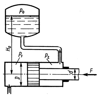
A thin-walled vessel consisting of two cylinders with diameters d= 100 mm and D\u003d 500 mm, the lower open end is lowered under the water level in tank A and rests on supports C located at a height b= 0.5 m above this level.
Determine the magnitude of the force perceived by the supports if a vacuum is created in the vessel, causing the water to rise to a height in it a + b= 0.7 m. Own weight of the vessel G= 300 N. How does changing the diameter affect the result d?

Task 1.7
Determine the absolute pressure of the air in the vessel if the indication of the mercury instrument h= 368 mm, height H\u003d 1 m. The density of mercury ρ rt \u003d 13600 kg / m 3. Atmosphere pressure p atm = 736 mm Hg Art.

Task 1.9
Determine the pressure above the piston p 01 if known: piston forces P 1 = 210 N, P 2 = 50 N; instrument reading p 02 = 245.25 kPa; piston diameters d 1 = 100 mm, d 2 = 50 mm and height difference h= 0.3 m. ρ RT / ρ = 13.6.

Task 1.16
Determine the pressure p in the hydraulic system and the weight of the load G lying on the piston 2 , if for its rise to the piston 1 applied force F= 1 kN. Piston diameters: D= 300 mm, d= 80 mm, h\u003d 1 m, ρ \u003d 810 kg / m 3. Build Graph p = f(D), if D varies from 300 to 100 mm.

Problem 1.17.
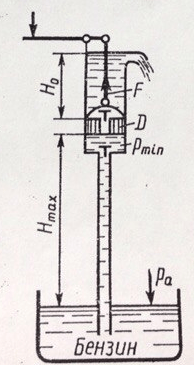
Determine the maximum height H max , to which gasoline can be sucked in by a piston pump, if its saturated vapor pressure is h n.p. = 200 mmHg Art., a Atmosphere pressure h a = 700 mm Hg. Art. What is the force along the rod, if H 0 \u003d 1 m, ρ b \u003d 700 kg / m 3; D= 50 mm?
Build Graph F = ƒ( D) when it changes D from 50 mm to 150 mm.
Task 1.18
Determine Diameter D 1 hydraulic cylinder required to lift the valve when liquid is pressurized p= 1 MPa if the pipeline diameter D 2 = 1 m and the mass of the moving parts of the device m= 204 kg. When calculating the friction coefficient of the valve in the guide surfaces, take f= 0.3, the friction force in the cylinder is considered equal to 5% of the weight of the moving parts. The pressure downstream of the valve is equal to atmospheric pressure, the effect of the stem area is neglected.
Plot dependency graph D 1 = f(p), if p varies from 0.8 to 5 MPa.

Task 1.19
When the hydraulic accumulator is charged, the pump supplies water to cylinder A, lifting plunger B with the weight up. When the accumulator is discharged, the plunger, sliding down, squeezes out the water from the cylinder into the hydraulic presses under the action of gravity.
1. Determine the water pressure when charging p h (developed by the pump) and discharge p p (obtained by the presses) of the accumulator, if the mass of the plunger together with the load m= 104 t and plunger diameter D= 400 mm.
The plunger is sealed with a cuff, the height of which b= 40 mm and coefficient of friction on the plunger f = 0,1.
Build Graph p h = f(D) and p p = f(D), if D varies from 400 to 100 mm, consider the mass of the plunger with the load unchanged.

Task 1.21
In a hermetically sealed feeder BUT there is molten babbitt (ρ = 8000 kg / m 3). At the indication of the vacuum gauge p vac = 0.07 MPa ladle filling B stopped. Wherein H= 750 mm. Determine the height of the babbit level h in the feeder BUT.

Task 1.23
Determine strength F necessary to keep the piston at a height h 2 = 2 m above the surface of the water in the well. A column of water rises above the piston h 1 = 3 m. Diameters: piston D= 100 mm, stem d= 30 mm. The weight of the piston and rod is ignored.

Task 1.24
The vessel contains molten lead (ρ = 11 g/cm3). Determine the pressure force acting on the bottom of the vessel if the height of the lead level h= 500 mm, vessel diameter D= 400 mm, pressure gauge reading p vac = 30 kPa.
Construct a graph of the dependence of the pressure force on the diameter of the vessel, if D varies from 400 to 1000 mm

Task 1.25
Determine the pressure p 1 fluid that must be brought to the hydraulic cylinder in order to overcome the force directed along the rod F= 1 kN. Diameters: cylinder D= 50 mm, stem d= 25 mm. Tank pressure p 0 = 50 kPa, height H 0 = 5 m. The force of friction is not taken into account. Liquid density ρ = 10 3 kg/m 3 .
Task 1.28
The system is in balance. D= 100 mm; d= 40 mm; h= 0.5 m.
What force must be applied to pistons A and B if a force is acting on piston C P 1 = 0.5 kN? Ignore friction. Plot dependency graph P 2 from diameter d, which varies from 40 to 90 mm.

Task 1.31
Determine strength F on the spool rod, if the vacuum gauge reading p vac = 60 kPa, overpressure p 1 = 1 MPa, height H= 3 m, piston diameters D= 20 mm and d\u003d 15 mm, ρ \u003d 1000 kg / m 3.
Build Graph F = f(D), if D varies from 20 to 160 mm.

Task 1.32
A system of two pistons connected by a rod is in equilibrium. Determine strength F compressing the spring. The liquid between the pistons and in the tank is oil with a density of ρ = 870 kg/m 3 . Diameters: D= 80 mm; d= 30 mm; height H= 1000 mm; overpressure R 0 = 10 kPa.

Task 1.35
Determine load P for cover bolts A and B hydraulic cylinder diameter D= 160 mm, if the plunger diameter d= 120 mm applied force F= 20 kN.
Plot dependency graph P = f(d), if d varies from 120 to 50 mm.

A task1.37
The figure shows a structural diagram of a hydraulic lock, the passage section of which opens when it is fed into the cavity BUT control fluid flow with pressure p y . Determine at what minimum value p y piston pusher 1 will be able to open the ball valve if it is known: spring preload 2 F= 50H; D = 25 mm, d = 15 mm, p 1 = 0.5 MPa, p 2 = 0.2 MPa. Ignore the forces of friction.

Problem 1.38
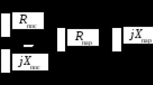
Determine Gauge Pressure p m, if the force on the piston P= 100 kgf; h 1 = 30 cm; h 2 = 60 cm; piston diameters d 1 = 100 mm; d 2 = 400 mm; d 3 = 200 mm; ρ m / ρ in = 0.9. Define p m.

Task 1.41
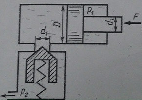
Determine the minimum value of the force F applied to the rod, under the action of which the movement of the piston with a diameter D= 80 mm if the spring force pressing the valve against the seat is F 0 = 100 H, and the liquid pressure p 2 = 0.2 MPa. Valve inlet diameter (seat) d 1 = 10 mm. Rod diameter d 2 = 40 mm, liquid pressure in the rod end of the hydraulic cylinder p 1 = 1.0 MPa.
Problem 1.42
Determine the amount of preload of the differential spring safety valve(mm), providing the beginning of the opening of the valve at p n = 0.8 MPa. Valve diameters: D= 24 mm, d= 18 mm; spring rate With= 6 N/mm. The pressure to the right of the larger and to the left of the small pistons is atmospheric.

Problem 1.44
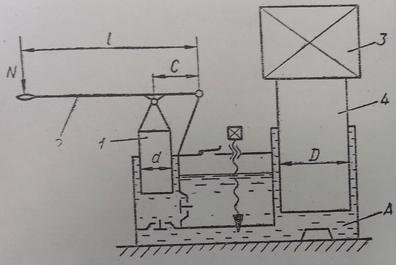
In a hydraulic jack with manual drive(fig. 27) at the end of the lever 2 effort made N= 150 N. Diameters of pressure 1 and lifting 4 plungers are respectively equal: d= 10 mm and D= 110 mm. Small lever arm With= 25 mm.
Taking into account the overall efficiency of the hydraulic jack η = 0.82, determine the length l lever 2 enough to lift the load 3 weighing 225 kN.
Plot dependency graph l = f(d), if d varies from 10 to 50 mm.
Task 1.4 5
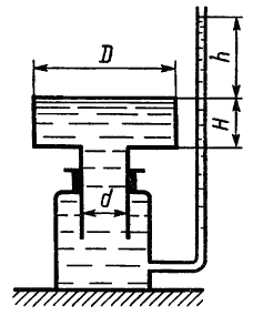
Determine Height h column of water in a piezometric tube. The column of water balances the full piston with D= 0.6 m and d= 0.2 m, having a height H= 0.2 m. Ignore the self-weight of the piston and the friction in the seal.
Build Graph h = f(D), if the diameter D varies from 0.6 to 1 m.
Task 1.51
Determine piston diameter = 80.0 kg; depth of water in cylinders H= 20 cm, h= 10 cm.
Build dependency P = f(D), if P= (20…80) kg.
Problem 1.81
Determine the reading of a two-fluid manometer h 2 if the pressure on the free surface in the tank p 0 abs = 147.15 kPa, water depth in the tank H= 1.5 m, distance to mercury h 1 \u003d 0.5 m, ρ rt / ρ in \u003d 13.6.

Task 2.33
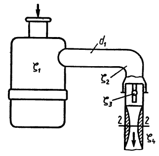
Air is sucked in by the engine from the atmosphere, passes through the air cleaner and then through a pipe with a diameter of d 1 = 50 mm is fed to the carburetor. Air density ρ \u003d 1.28 kg / m 3. Determine the vacuum in the neck of the diffuser with a diameter d 2 = 25 mm (section 2-2) with air flow Q\u003d 0.05 m 3 / s. Accept the following resistance coefficients: air cleaner ζ 1 = 5; knee ζ 2 = 1; air damper ζ 3 \u003d 0.5 (related to the speed in the pipe); nozzle ζ 4 = 0.05 (related to the velocity in the diffuser neck).
Problem 18
To weigh heavy loads 3 weighing from 20 to 60 tons, a hydrodynamometer is used (Fig. 7). Piston 1 diameter D= 300 mm, stem 2 diameter d= 50 mm.
Neglecting the weight of the piston and rod, plot the pressure readings R pressure gauge 4 depending on weight m cargo 3.
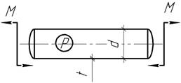
Problem 23
On fig. 12 shows a diagram of a hydraulic valve with a spool with a diameter d= 20 mm.
Neglecting the friction in the hydraulic valve and the weight of the spool 1, determine the minimum force that the compressed spring 2 must develop to balance the oil pressure in the lower cavity A R= 10 MPa.
Plot the spring force versus diameter d, if d varies from 20 to 40 mm.

Problem 25
On fig. 14 shows a diagram of a hydraulic valve with a flat valve 2 diameter d= 20 mm. In the pressure cavity AT hydraulic valve oil pressure p= 5 MPa.
Neglecting the backpressure in the cavity BUT hydraulic distributor and the force of a weak spring 3, determine the length l lever arm 1, sufficient to open the flat valve 2 applied to the end of the lever by force F= 50 N if the length of the small arm a= 20 mm.
Plot dependency graph F = f(l).

Task 1.210
On fig. 10 shows a diagram of a plunger pressure switch, in which, when plunger 3 moves to the left, pin 2 rises, switching electrical contacts 4. Spring stiffness coefficient 1 FROM= 50.26 kN/m. The pressure switch is triggered, i.e. switches electrical contacts 4 with axial deflection of spring 1 equal to 10 mm.
Neglecting friction in the pressure switch, determine the diameter d plunger, if the pressure switch should operate at oil pressure in cavity A (at the outlet) R= 10 MPa.

A taskI.27
Hydraulic intensifier (device for increasing pressure) receives pressurized water from the pump p 1 = 0.5 MPa. At the same time, a movable cylinder filled with water BUT with outside diameter D= 200 mm slides on a fixed rolling pin FROM, having a diameter d= 50 mm, creating pressure at the outlet of the multiplier p 2 .
Determine the pressure p 2, assuming the friction force in the glands equal to 10% of the force developed on the cylinder by pressure p 1 and neglecting the pressure in the return line.
Mass of moving parts of the multiplier m= 204 kg.
Plot dependency graph p 2 = f(D), if D varies from 200 to 500 mm, m, d, p 1 to be considered constant.

You can buy tasks or order new ones by e-mail (skype)
Task 2. Hydrostatics
Option 0
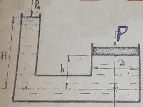
A thin-walled vessel, consisting of two cylinders with diameters D and d, is lowered with its lower open end under the liquid level G in tank A and rests on supports C located at a height b above this level. Determine the force perceived by the supports if a vacuum is created in the vessel, which causes the liquid F to rise in it to a height (a + b). The mass of the vessel is m. How does a change in diameter d affect this force? The numerical values of these quantities are given in Table 2.0.
Table 2.0
|
liquid |
||||||
|
Fresh water |
||||||
|
Diesel fuel |
||||||
|
Heavy oil |
||||||
|
Oil AMG-10 |
||||||
|
Transformer |
||||||
|
Spindle |
||||||
|
Turbine |
||||||
|
Light oil |
Option 1

A cylindrical vessel, having a diameter D and filled with liquid to a height a, hangs without friction on a plunger with a diameter d (Fig. 2.1). Determine the vacuum V, which ensures the equilibrium of the vessel, if its mass with lids is m. How do the diameter of the plunger and the depth of its immersion in the liquid affect the result? Calculate the forces in the bolted connections B and C of the vessel. The weight of each cover is 0.2 m. The numerical values of these quantities are given in Table 2.1.
Table 2.1
|
Liquid |
|||||
|
Light oil |
|||||
|
Diesel fuel |
|||||
|
Heavy oil |
|||||
|
Oil AMG-10 |
|||||
|
transformer |
|||||
|
Spindle |
|||||
|
Turbine |
|||||
|
Industrial 20 |
Option 2
 The closed tank is divided into two parts by a flat partition, which has a square hole with side a at a depth h, closed by a lid (Fig. 2.2). The pressure above the liquid in the left side of the tank is determined by the reading of the pressure gauge p M, the air pressure in the right side is determined by the reading of the vacuum gauge p V . Determine the magnitude of the hydrostatic pressure force on the lid. The numerical values of these quantities are given in Table 2.2.
Table 2.2
|
Liquid |
|||||
|
Diesel fuel |
|||||
|
Light oil |
|||||
|
Heavy oil |
|||||
|
Oil AMG-10 |
|||||
|
Turbine |
|||||
|
Spindle |
|||||
|
transformer |
|||||
|
Industrial 12 |
Calculation of thin-walled vessels according to the momentless theory
Task 1.
The air pressure in the cylinder of the suspension strut of the aircraft landing gear in the parking position is p = 20 MPa. Cylinder diameter d =….. mm, wall thickness t =4 mm. Determine the main stresses in the cylinder in the parking lot and after takeoff, when the pressure in the shock absorber is ………………….
Answer: (in the parking lot); (after takeoff).
Task 2.
Water enters the water turbine through a pipeline, the outer diameter of which at the machine building is equal to .... m, and the wall thickness t =25 mm. The machine building is located 200 m below the level of the lake from which water is taken. Find the maximum voltage in ……………………….
Answer:
Task 3.
Check the strength of the wall …………………………… with a diameter of ….. m, under operating pressure p = 1 MPa, if the wall thickness t =12 mm, [σ]=100 MPa. Apply IV strength hypothesis.
Answer:
Task 4.
The boiler has a diameter of the cylindrical part d =…. m and is under operating pressure p=….. MPa. Select the boiler wall thickness at the allowable stress [σ]=100 MPa using III strength hypothesis. What would be the required thickness when using IV strength hypotheses?
Answer:
Task 5.
Steel spherical shell diameter d =1 m and thickness t =…. mm loaded with internal pressure p = 4 MPa. Determine……………… stress and ……………….. diameter.
Answer: mm.
Task 6.
Cylindrical vessel diameter d =0.8 m has a wall thickness t =… mm. Determine the value of the allowable pressure in the vessel, based on IV strength hypotheses, if [σ]=…… MPa.
Answer: [p]=1.5 MPa.
Task 7.
Define ………………………….. of the material of the cylindrical shell, if, when loading it with internal pressure, the deformations in the direction of the sensors amounted to
Answer: v=0.25.
Task 8.
Duralumin tube thicknessmm and inner diametermm is reinforced with a steel shirt with a thickness ofmm. Find the ultimate ………………………..for a two-layer pipe in terms of the yield strength and ……………… the stress between the layers at this moment, assuming E st = 200 GPa,E d \u003d 70 GPa,
Answer:
Task 9.
Conduit diameter d =…. mm during the start-up period had a wall thickness t =8 mm. During operation due to corrosion, the thickness in some places……………………... What is the maximum column of water that the pipeline can withstand with a double safety margin, if the yield strength of the pipe material is
Task 10.
Gas pipeline diameter d =……. mm and wall thickness t = 8 mm crosses the reservoir at a maximum………………………….., reaching 60 m. During operation, gas is pumped under pressure p = 2.2 MPa, and during the construction of an underwater crossing, there is no pressure in the pipe. What are the greatest stresses in the pipeline and when do they occur?
Task 11.
The thin-walled cylindrical vessel has hemispherical bottoms. What should be the ratio between the thicknesses of the cylindrical and spherical parts so that in the transition zone there is no ………………….?
Task 12.
In the manufacture of railway tanks, they are tested under pressure p = 0.6 MPa. Determine ………………………… in the cylindrical part and in the bottom of the tank, taking the pressure during testing as the design pressure. Calculate according to III strength hypotheses.

Task 13.
Between two concentrically located bronze pipes, a liquid flows under pressure p = 6 MPa. The thickness of the outer pipe isAt what thickness of the inner tubeprovided by …………………….. of both pipes? What is the maximum voltage in this case?

Task 14.
Determine ………………………… of the shell material, if, when loading it with internal pressure, the deformations in the direction of the sensors amounted to

Task 15.
Thin-walled spherical vessel with a diameter d =1 m and thickness t \u003d 1 cm is under the action internal pressure and external What is ………………….. vessel P t if
Would the following be correct:

Task 16.
A thin-walled pipe with plugged ends is under the action of internal pressure p and bending moment M. Using III strength hypothesis, investigate …………………… stresseson the value of M for a given p.
Task 17.
At what depth are the points with ………………….. meridional and circumferential stresses for the conical vessel shown on the right? Determine the magnitude of these stresses, assuming the specific gravity of the product is equal to γ=…. kN/m 3 .

Task 18.
The vessel is subjected to gas pressure p = 10 MPa. Find…………………… if [σ]=250 MPa.

Answer: t =30 mm.
Task 19.
A vertically standing cylindrical tank with a hemispherical bottom is filled to the top with water. Thickness of side walls and bottom t =2 mm. Define ………………………. stresses in the cylindrical and spherical parts of the structure.
Answer:
Task 20.
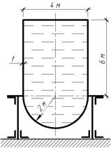
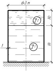
The cylindrical tank is supplemented to a depth of H 1 = 6 m with a liquid with a specific gravityand on top not - to a thickness of H 2 \u003d 2 m - with water. Determine …………………….. tank at the bottom, if [σ]=60 MPa.
Answer: t =5 mm.
Task 21.
A small gas tank for lighting gas has a wall thickness t =5 mm. Find ………………………………… upper and lower vessels.

Answer:
Task 22.
The float valve of the testing machine is a closed aluminum alloy cylinder with a diameter of d =….. mm. The float is subjected to ………………………pressure p =23 MPa. Determine the float wall thickness using the fourth strength hypothesis if [σ]=200 MPa.

Answer: t =5 mm.
Task 23.
A thin-walled spherical vessel with a diameter d =1 m and thickness t \u003d 1 cm is under the influence of internal ……………… and external What is ……………….. vessel walls if

Answer: .
Task 24.
Determine the largest ………………… and circumferential stresses in a toroidal balloon, if p=…. MPa t =3 mm, a=0.5 mm; d = 0.4 m.

Answer:
Task 25.
Steel hemispherical vessel of radius R =… m is filled with a liquid with specific gravity γ=7.5 kN/m 3 . Taking ……………………. 2 mm and using III strength hypothesis, determine the required thickness of the vessel wall if [σ]=80 MPa.

Answer: t =3 mm.
Task 26.
Determine, …………………… there are points with the highest meridional and circumferential stresses and calculate these stresses if the wall thickness t =… mm, specific gravity of the liquid γ=10 kN/m 3 .

Answer: at a depth of 2 m; at a depth of 4 m.
Task 27.
A cylindrical vessel with a conical bottom is filled with a liquid with a specific gravity of γ=7 kN/m 3 . The wall thickness is constant and equal to t =…mm. Define …………………………….. and circumferential stresses.

Answer:
Task 28.
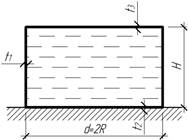
A cylindrical vessel with a hemispherical bottom is filled with a liquid with specific gravity γ=10 kN/m 3 . The wall thickness is constant and equal to t =… mm. Determine the maximum stress in the vessel wall. How many times will this voltage increase if the length is………………………………, keeping all other dimensions unchanged?

Answer: will increase by 1.6 times.
Task 29.
To store oil with a specific gravity of γ=9.5 kN/m3, a vessel in the form of a truncated cone with a wall thickness t =10 mm. Determine the largest …………………………. stress in the vessel wall.

Answer:
Task 30.
The thin-walled conical bell is under a layer of water. Determine …………………………….. and circumferential stresses, if the air pressure on the surface under the bell wall thickness t =10 mm.

Answer:
Task 31.
Shell thickness t =20 mm, having the shape of an ellipsoid of rotation (Ox - axis of rotation), loaded with internal pressure p=…. MPa. Find ………………….. in longitudinal and cross sections.
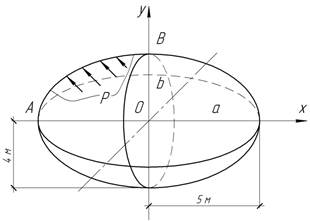
Answer:
Task 32.
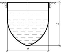
Using the third strength hypothesis, check the strength of a vessel having the shape of a paraboloid of revolution with wall thickness t =… mm, if the specific gravity of the liquid γ=10 kN/m 3 , allowable stress [σ]=20 MPa, d=h \u003d 5 m. Check strength in height…………………………...
Answer: those. strength is guaranteed.
Task 33.
Cylindrical vessel with spherical bottoms is intended for gas storage under pressure р =… MPa. Under ………………… it will be possible to store gas in a spherical vessel of the same capacity with the same material and wall thickness? What is the savings in material?

Answer: savings will be 36%.
Task 34.
Cylindrical shell with wall thickness t =5 mm compressed force F=….. kN. The forming shells, due to inaccuracies in manufacturing, received a small…………………………. Neglecting the effect of this curvature on the meridional stresses, calculatein the middle of the shell height under the assumption that the generators are curved along one half-wave of the sinusoid, and f=0.01 l; l=r.

Answer:
Task 35.
Vertical cylindrical vessel designed to store liquid volume V and specific gravity γ. The total thickness of the upper and lower bases, assigned for design reasons, is equal toDetermine the most advantageous height of the tank H opt , at which the mass of the structure will be minimal.Taking the tank height equal to H opt , find ………………………….. parts, assuming [σ]=180 MPa, Δ=9 mm, γ=10 kN/m 3 , V \u003d 1000 m 3.
Answer: N opt \u003d 9 m, mm.
Task 36.
Long thin tube t =…. mm is put with an interference fit Δ on an absolutely rigid rod of diameter d =….. mm . …………… must be attached to the tube in order to remove it from the rod if Δ=0.0213 mm; f=0.1; l=10 cm, E=100 GPa, ν=0.35.

Answer: F=10 kN.
Problem 37.
A thin-walled cylindrical vessel with spherical bottoms is subjected from the inside to a gas pressure p = 7 MPa. By ……………………………….. diameter E 1 \u003d E 2 \u003d 200 GPa.

Answer: N 02 \u003d 215 N.
Problem 38.
Among other structural elements in aviation and rocket technology, cylinders are used high pressure. They are usually cylindrical or spherical in shape and, like other structural components, it is extremely important to comply with the minimum weight requirement. The design of the shaped cylinder shown in the figure is proposed. The walls of the container consist of several cylindrical sections connected by radial walls. Since the cylindrical walls have a small radius, the stresses in them decrease, and it can be hoped that despite the increase in weight due to the radial walls, the total weight of the structure will be less than for an ordinary cylinder having the same volume……………………… …….?

Task 39.
Determine ……………………… a thin-walled shell of equal resistance containing a liquid of specific gravity γ.

Calculation of thick-walled pipes
Task 1.
What pressure (internal or external) ……………………. pipes? How many times the highest equivalent stresses III hypothesis of strength in one case more or less than in the other, if the pressures are the same? Will the largest radial displacements be equal in both cases?
Task 2.
The two pipes differ only in size. cross section: 1st trumpet - a=20 cm, b =30 cm; 2nd pipe - a=10 cm, b \u003d 15 cm. Which of the pipes has ……………………… the ability?
Task 3.
Thick wall pipe with dimensions a=20 cm and b \u003d 40 cm does not withstand the specified pressure. In order to increase the bearing capacity, two options are offered: 1) increase the outer radius by P times b ; 2) reduce the inner radius by P times a. Which of the options gives ……………………………. with the same value of P?
Task 4.
Pipe with dimensions a=10 cm and b \u003d 20 cm withstand pressure p \u003d ... .. MPa. To what extent (in percent) ……………….. the bearing capacity of the pipe, if the outer radius is increased by … times?
Task 5.
At the end of the First World War (1918), an ultra-long-range cannon was manufactured in Germany to bombard Paris from a distance of 115 km. It was steel pipe 34 m long and 40 cm thick walls in the breech. The gun weighed 7.5 MN. Its 120-kilogram projectiles were a meter long with a diameter of 21 cm. For the charge, 150 kg of gunpowder was used, developing a pressure of 500 MPa, which ejected the projectile with an initial speed of 2 km / s. What should be……………………………., used to make the gun barrel, if not less than one and a half times the margin of safety?