Distillation tray columns, diopters. Bubble-bottom tray Sensitivity to control actions
As planned in the previous one, I tested the poppet insert. In fact, such an insert is one of the variations of the nozzle for mash columns.
Why for gentlemen? That it is impossible to get alcohol on the tray column, of which this insert is a part? In principle, of course, you can also take a swing at alcohol - that's just very irrational. Remember, in one of those dedicated to the theory of rectification, I wrote that to get alcohol you need to have at least 50 plates. Considering that the height of the conditional plate for the SPN nozzle is about 2 cm, and the distance between the physical plates is approximately equal to the diameter with real efficiency in around 85% (compared to a theoretical tray, such sieve trays do not give an adequate separation effect), then the actually comparable height of such a tray column will be 2.5-3 times greater than that of a column with SPN packing, with equal opportunities. So it turns out that the construction of the RC on sieve plates is the lot of people who are obsessed with a passion for plate structures, but on the BK, where the task of deep separation is not set in principle (the goal is distillate), the use of such plates is justified.
In addition, plates have advantages over SPN and washcloths in BC - plates are easy to clean and less clogged. The main thing is to choose the right diameter and number of holes and the dimensions of the plate itself. Here my insert is in some contradiction with the dogma that has been formed recently that there is nothing to do with plates with a diameter of less than 50mm, but what can I do - I have a 38 pipe with an inner diameter of 35mm. From this we will proceed.
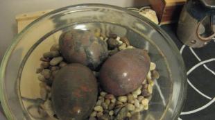
So, an insert of 7 PTFE plates was placed in an empty drawer with a height of 500 mm, the total length of the insert was 270 mm. In each plate there are 22-25 (and in one there are 30 at all) holes with a diameter of 3 mm, randomly drilled for an additional “swirl” of steam. Why exactly? I find it difficult to answer - it seemed to me that this would be correct, although I do not insist on this opinion. By the way, the cymbals are too loose and it was quite possible to put at least one more cymbal on the same insert. The whole process was carried out on a turntable with a large aftercooler, the CC was diluted to about 12%.
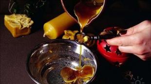
Heads were first sampled at a rate of one drop per second. Then began the selection of the body. An insert with plates made it possible to obtain a stable temperature of the steam passing into the reflux condenser. By varying the sampling rate (by pinching the sampling tube with a Hoffmann clamp), it was possible to influence this temperature. I was quite satisfied with the readings of the thermometer at the level of 79 ° C with a selection of 2.4 l / h. By the end of the process, the output dropped slightly to about 2.1 l/h. On the readings of the thermometer in a cube of 96°C, I stopped the selection of a marketable product and switched to tailings. Further, the productivity began to fall more noticeably, and at a temperature in the cube of about 98 ° C, the selection became very small. Attempts to increase power and selection did not lead to success, since isoamyl began to pass through TCA. This point is not entirely clear to me. Either some non-condensable gases are formed, or the performance of the CT in the reflux mode was not enough (which is doubtful at the powers that I gave). There is one more experiment ahead - you need to either drive the CT as a dephlegmator (maybe its capabilities are insufficient, which is strange), or repeat the experiment with the insert on the already tested def with dimrot.
Summary . At the output, a product with a strength of 80 ° was obtained. Not thick, but for the purposes of bourbon building it is quite suitable. It can be considered as a variant of a relatively simple nozzle for distillers with reinforcement. It remains to be compared with a small sample of SPN and just a really empty drawer side. And, by the way, I made a mistake during the experiment - I did not insulate the empty tsarga, which became a packing. In general, the field ahead is not plowed.
Interestingly, the fortress did not change the entire shoulder strap (even on the heads there were the same 80 °) to the tails, but it began to fall very sharply when moving to the tails. Also, in general, it is strange for the heads. I'll play with the cymbals, perhaps.
Modular plate column. Practice on automation BKU - 011M.
Copper cone lids. A column of copper flavor. Theory and practice.
Alcohol mashine. Cap column HD/3-500 KKS-N. Part 1. New in 2016.
Alcohol mashine. Cap column HD/3-500 KKS-N. Part 2. New in 2016.
Alcohol mashine. Plate column.
What is a tray column and why is it needed at all ... The essential difference from the tsargi is that in the tray column we use the tray itself instead of the SPN packing (spiral prismatic packing). With the help of a tray column, we will not get pure alcohol. However, we can get on it the so-called under-rectification with a strength of 90-95 vol. That is, it is also not alcohol, but it is no longer a distillate. A very highly refined distillate that still retains notes of the original raw material. This technology has been used for more than a hundred years, and it is actively used by distillers around the world. Our country in this sense has not been an exception in recent years. These columns are gaining immense popularity.
Let us analyze the main differences between the columns for a correct understanding of the choice of a particular column.
- Like all our equipment, tray columns are distinguished by series: HD/4 or HD/3. Everything is simple here. If you already have HD equipment, the choice is made according to the corresponding series of equipment. If you are only going to purchase equipment, then you need to understand the difference between the HD / 4 and HD / 3 series. The HD/4 series is more budgetary, it has an optimal price-quality ratio. The HD/3 series has a higher price but also higher performance.
- Materials used in the manufacture of columns. It is either food grade stainless steel or quartz glass. In the latter case, you have the opportunity to observe the process visually, which is a real pleasure. Do not forget that in the first place we do this hobby for the sake of pleasure.
- The columns also differ in height and in the number of plates in them. The height of the column comes in two sizes: 375 and 750 mm, respectively. On a shortened column, you can get "under-rectified" with a strength of 91-92C, on a column of 750 mm you can get "under-rectified" about 95C. Since the disc columns are collapsible, the number of plates in the column can be adjusted by the distiller independently.
- Plate execution type. Plates are made of two types: failure and cap. It is difficult to say unequivocally which of the plates is better and on which plates the drink will turn out tastier. The fact is that failure plates are good if we use a stable heating power, without jumps in the network. If the network is unstable, then you can use a heating power stabilizer for example. The cap-type plates are more unpretentious and any heating can be used. However, due to the complexity of manufacturing such columns, they are more expensive. But also more aesthetic in the process.
- Plate making materials. Failed plates are made of inert PTFE. Cap cymbals are made from either stainless steel or copper. Stainless steel is known to be inert. And therefore, the drink obtained on its surface does not have any characteristic additional tastes, except for the original raw material. Copper, on the other hand, is believed to absorb harmful sulfur released during the distillation process, thereby ridding the drink of unpleasant odors and taste. Supporters of copper and stainless steel have many fans. Everyone has their own arguments in favor of the material used for the plates.
You can learn more about working with disc columns here.
(5 4 V 01 V 3/22 DESCRIPTION OF THE INVENTION TO TEPSTVO AUTHOR’S U 6ilial Voroshins SSRO.RELKA stvo S 2, 198 ) The invention relates to the designs of failed tare apparatuses and can be used in the chemical industry, in particular in the processing of acids.The purpose of the invention is to intensify the mass transfer process by increasing the phase contact surface and reducing material consumption without reducing mechanical strength.The plate includes a plate 1 with holes 2 of different sizes, side walls 3 of which made in the form of tetrahedral truncated pyramids with rounded ribs and a cylindrical bore in the narrowed part, with large bases of large holes located on the upper side of the plate. The purpose of the invention is to intensify the mass transfer process by increasing the phase contact surface and reducing the material consumption without reducing the mechanical strength. FIG. 1 shows a plate, top view; in fig. 2 - the same, bottom bottom; in fig. 3 - section A-A in Fig. one; in fig. four - cut B-B in fig. 2. The bubbling failure plate includes a plate 1 with holes 2 of various sizes, the side walls 3 of which are made in the form of four-sided truncated pyramids with rounded ribs and a cylindrical bore in the narrowed part, as well as with a conical chamfer. In this case, the large bases of the large holes are located on the upper side of the tray. It is also advisable to arrange holes of various sizes in alternating rows. The gas coming from the underlying plate into the cylindrical bore of the pyramidal hole bubbles through the formed layer of liquid, thereby increasing the phase contact surface. The design features of this tray make it possible to make better use of its working surface. The tray can be made from a ferroalloy by casting or from a fluoroplastic by pressing. a - yuschaya with the fact that, in order to intensify the mass transfer process by increasing the contact surface of the FAE and reducing the material consumption without reducing the mechanical strength, the side walls of the holes are made in the form of tetrahedral truncated pyramids with rounded ribs and cylindrical with a bore in the narrowed part, with the large bases of the large holes located on the upper side of the plate.
Request
3875425, 26.03.1985
RUBEZHANSK BRANCH OF VOROSHILOVGRAD MACHINE-BUILDING INSTITUTE
ZINCHENKO Igor Maksimovich
IPC / Tags
Link code
Bubbling failure tray
Related Patents
The inlet is equipped with a technological cover 11 with a protrusion 12, with a height not less than the wall thickness of the side inlet, installed into it with a minimum clearance. connector is not disassembled, Vessel high pressure are made as follows: A body 1 is made with a side opening, a branch pipe is welded in, a technological cover 11 is installed on the received side inlet. input. For sealing...
A smaller working step shank is installed in a free fit, serving as a guide for a larger working step. The proposed tool is shown in the drawing. Step 1 is installed with the guide part in hole 3 of the part, then step 2 is put on the shank of step 1 with a blind hole, and the guide part enters hole 4 of the part. Under the action of the rod of the power element, both steps simultaneously move in the direction of movement of the rod. At the end of the working stroke of the tool, stage 1 is separated from stage 2 under the action of gravity, ...
The cores of transformers 12, and buses 8 are connected to them, combining the windings of 6 cores corresponding to the numbers 1. Primary windings 16 are sewn in the opposite direction with the cores of transformers 11 and in the forward direction - the cores of transformers 12, and buses 8 are connected to them, combining winding b cores corresponding to the numbers 2. Primary. the cores of transformers 11 and 12 are sewn with reverse windings 16, and buses 8 are connected to them, combining the windings of the b cores corresponding to the numbers 3. The secondary windings 17 are the outputs of the decoders 9, and playback amplifiers 18 are connected to them. The number of outputs of the decoders 9 is two (generally 1 oddr, the device works as follows...
Disc columns for distillation have a small strengthening ability and are traditionally used in the production of whiskey, cognac and other noble drinks. A small number of plates allows you to save the organoleptic of raw materials with high stability and productivity of the apparatus.
Material
Copper dish-shaped columns with viewing windows are called flutes because of their similarity, and those made in a glass case are called crystal. It is clear that these names are just a marketing ploy and have nothing to do with the design itself.
Copper is an expensive material, so the approach to its processing is thorough. A brass flute from leading manufacturers is a work of art and a source of their pride. The cost of the product can be absolutely any amount that the buyer is willing to spend.
A little cheaper than a flute in a stainless steel case, and the most budget option is in a glass case.

Design features and types of dish columns
The most widespread are modular column designs based on branch tees or cylinders made of borosilicate glass. Naturally, this is a large number of extra connecting parts and an overestimated cost.
A simpler option is ready blocks for 5-10 plates. Here the choice is wider, and the price is more moderate. As a rule, this option is made in glass cases.
There are absolutely budget options- just inserts for existing drawers.

They can be recruited from components in any required quantity.

The design may be different, but if such tray columns are used with metal flasks, the visibility of the process is lost. It is much more difficult to understand what mode the column is operating in, and this is very important for working with plates.
To seal each floor, simple silicone discs are used.

Naturally, this is less reliable than sealing gaskets in modular designs, but in general they work well.

As an alternative, there is a simplified modular design, where each floor is assembled from simple and inexpensive parts, and the entire structure is pulled together with studs.
The advantage of modular columns is primarily their maintainability and openness to modifications. For example, it is easy to supplement the column at the required level with an intermediate fractionation unit and a fitting for a thermometer. All you have to do is change the plate.

Sieve tray columns are a cheaper option. This does not mean that the quality of the product with their use will be worse. But they require more precise control.

Dip trays are even cheaper, but their operating range is very narrow, so you need to be prepared for precise heat control with power stabilized sources. Basically, failed trays are used at the NSC.
The most common materials for making cymbals are copper, stainless steel and PTFE. Any combination is possible. Copper and stainless steel are familiar materials, fluoroplastic is one of the most inert materials, comparable to platinum. But its wettability is poor.
If we compare a fluoroplastic plate with a stainless one, then it will be flooded much faster.
The number of plates in the column is usually limited to 5 for distillates with a strength of 88-92% and 10 for purified distillates with a strength of up to 94-95%.
Modular columns allow you to make a set of the required number of plates from various materials.
Difference Between Packed Column and Tray Column
“I have a packed column, do I need a tray?” – this question sooner or later confronts every distiller. Both columns implement the heat and mass transfer technology, but there are significant differences in their operation.
Number of reinforcement steps
The packed column operates in the maximum separation mode at the pre-choke capacity. By adjusting the reflux ratio, it is possible to change the number of theoretical plates in a wide range: from zero to infinity (with the reflux condenser completely turned off and the column working on itself).
The tray column is characterized by a structurally specified number of separation stages. One physical plate has an efficiency of 40 to 70%. In other words, two physical plates give one stage of separation (strengthening, theoretical plate). Depending on the operating mode, the efficiency does not change so much as to significantly affect the number of steps.
holding capacity
A packed column with its low holding capacity makes it possible to well purify the distillate from the head fraction and somehow contain the tail fraction.
The tray column has an order of magnitude greater holding capacity. This prevents her from doing such a hard cleaning of the "heads", but allows her to perfectly contain the tails. That is, to equalize the distillate according to chemical composition. Moreover, the more you need to clean the distillate from impurities, the more plates you need to put. Simple task, solvable in practice. Once you have found the optimal number of plates for yourself and you don’t think about it anymore.
Sensitivity to control actions
The packed column is very sensitive to the difference in water pressure in the reflux condenser or to changes in heating power. A slight change in them leads to a change in the number of strengthening steps at times or even dozens of times.
The efficiency of plates can change by a maximum of 1.5 times, and even then with a very large and targeted change in these parameters. It can be considered that a tuned tray column, in terms of separating power, will practically not respond to the usual small drops in water pressure or voltage.
Performance
The performance of a packed column mainly depends on its diameter. The optimal diameter for modern nozzles is 40-50 mm, with a further increase in the diameter, the stability of the processes decreases. Near-wall effects and channel formation begin to manifest themselves. Disc columns do not suffer from such weaknesses. Their diameter and productivity can be increased to any required value. If only there was enough heating power.
Technological features of obtaining aromatic distillates
When using packed columns to limit the degree of strengthening, we are forced to use shorter sides and a larger packing. Otherwise, the esters that give the main flavor to the distillate will create azeotropes with impurities of the head fraction, then quickly fly out of the cube. We select the “heads” shortly, the “body” - at an increased speed. As for the "tails", the small number of nozzles and the short tsarga do not completely contain the fuselage. It is necessary to switch to the selection of tail fractions earlier or to work with small cubic bulks.
The tray column has a relatively large holding capacity, so there are no questions about the retention of fusel oil. For the selection of "heads" and "body" 5-10 physical plates give 3-5 steps of strengthening. This allows distillation according to the rules of conventional distillation. Calmly, without the risk of depriving the distillate of aroma, select the "heads", and when collecting the "body" do not think about the premature approach of the "tails". Fogging on the lower plates at the end of the selection will clearly let you know about the need to change the container. The degree of cleaning can be set by changing the number of plates.
Five or ten plates are not enough to get close to alcohol in terms of purification, but it’s realistic to get into the GOST requirements for distillate.
The use of tray columns in the distillation of fruit or grain raw materials, especially for further aging in barrels, greatly simplifies the distiller's life.
Fundamentals of sizing column trays
Consider the designs of the most common plates for domestic purposes.
Failed plate
At its core, this is just a plate with holes, which can be round, rectangular, etc.
The phlegm flows into relatively large holes towards the steam, which determines the main disadvantage of failed plates - the need for precise control of the set mode.

A slight decrease in the heating power leads to the fact that the entire phlegm falls into the cube, and an increase in power locks the phlegm on the plate and leads to choking. These trays can operate satisfactorily over a relatively narrow load range, where they are quite competitive.
The simplicity of design and high performance of failed plates, along with the usual heating in home distilling by heating elements with a voltage-stabilized power source, led to their widespread use for continuous mash columns (NSC), which, in combination with a borosilicate or quartz glass body, makes column setup simple and intuitive.
To calculate the number and diameter of holes, the bubbling conditions are taken into account. It has been experimentally determined that the total area of the holes should be equal to 15-30% of the plate area (pipe section). In the general case, for BK of periodic action, the base diameter of the holes is about 9-10% of the diameter of the column allows you to get into the working area.
The diameter of the holes of the failure trays for the NSC is selected based on the properties of the raw material. If during distillation sugar mash and wine, holes with a diameter of 5-6 mm are enough, then when distilling flour jams, a hole diameter of 7-8 mm is preferable. However, trays for NSC have their own calculation features, since the vapor density varies significantly along the height of the column, the dimensions must be calculated for each tray separately, otherwise their performance will be far from optimal.
Sieve plate with overflow
If the diameters of the holes of the failed plate are less than 3 mm, then even at a relatively low power, the phlegm will be locked on the plate and without additional overflow devices, it will be flooded. But a sieve tray equipped with such devices significantly expands its operating range.
 Scheme of the sieve column device:
 1 - body; 2 - sieve plate; 3 - overflow tube; 4- glass
With the help of overflow devices on these plates, the maximum level of reflux is set, which allows you to avoid early flooding and more confidently work with a high steam load. This does not prevent the phlegm from completely merging into a cube when the heating is turned off, and the column will have to be restarted from scratch, as is usual for all failed plates.
In a simplified calculation of such plates, the following relationships are taken into account:
- the total area of the holes is 7-15% of the pipe cross-sectional area;
- the ratio between the diameters of the holes and the pitch between them is about 3.5;
- the diameter of the drain pipes is approximately 20% of the diameter of the dish.
Water seals must be installed in the drain holes to avoid steam breakthrough. Sieve plates must be installed strictly horizontally to allow steam to pass through all the holes and to prevent reflux from flowing through them.
capped plates
If, instead of holes in the plates, we make steam pipes higher than the drain pipes, and cover them with slotted caps, we get a completely new quality. These plates will not drain the phlegm when the heat is turned off. The phlegm divided into fractions will remain on the plates. Therefore, to continue working, it will be enough to turn on the heating.

In addition, such plates have a structurally fixed reflux layer on the surface, they operate in a wider range of heating powers (steam loads) and changes in reflux ratio (from complete absence to complete return of reflux).
It is also important that cap plates have relatively high efficiency- about 0.6-0.7. All this, along with the aesthetics of the process, determines the popularity of cap cymbals.
When calculating the construct, the following proportions are taken into account:
- the area of the steam tubes is about 10% of the section of the column;
- the area of the slots is 70-80% of the area of the steam pipes;
- drain area 1/3 of the total area of the steam pipes (diameter approximately 18-20% of the diameter of the pipe section);
- the lower plates are designed with a high level of reflux and a large section of the slots so that they work as holding ones;
- top plates are made with a lower reflux level and a cut section so that they work as a separating one.

Based on the graphs given by Stabnikov, we see that with a reflux layer of 12 mm (curve 2), the maximum efficiency is achieved at a steam velocity of the order of 0.3-0.4 m/s.
For a 2” column with an internal diameter of 48 mm, the required net heating power will be:
N = V * S / 750;
- V is the steam velocity in m/s;
- N is the power in kW, S is the sectional area of the column in mm².
N \u003d 0.3 * 1808 / 750 \u003d 0.72 kW.
You might think that 0.72 kW determines a small performance. Perhaps, taking into account the available power, it is worth increasing the diameter of the column? It's probably right. Common diameters of quartz glasses for diopters are 80, 108 mm. Let's take 80 mm with a wall thickness of 4 mm, an inner diameter of 72 mm, a cross-sectional area of 4069 mm². Let's recalculate the power - we get 1.62 kW. Well, better for home gas stove fits.
Having chosen the diameter of the column and the calculated power, we determine the height of the overflow pipe and the distance between the plates. To do this, we use the following equation:
V = (0.305 * H / (60 + 0.05 * H)) - 0.012 * Z (m/s);
- H is the distance between the plates;
- Z is the height of the overflow tube (i.e. the thickness of the reflux layer on the plate).
The steam speed is 0.3 m/s, the height of the plate should not be less than its diameter. For lower plates, the height of the reflux layer is larger. Smaller for the top.
Let's calculate the closest combinations of plate and overflow heights, mm: 90-11; 100-14; 110-18; 120-21. Taking into account the fact that standard glass has a height of 100 mm, for a modular design we choose a pair of 100-14 mm. Naturally, this is just our choice. You can take more, then the protection against spray will be better with an increase in power.
If the design is not modular, then there is more room for creativity. You can make the lower plates with a larger holding capacity of 100-14, and the upper one with a larger separation - 90-11.
We choose caps from standard and available sizes. For example, stubs for copper pipe 28 mm, steam pipes - pipe 22 mm. The height of the steam pipe must be greater than that of the overflow pipe, say 17 mm. The gaps for the passage of steam between the cap and the steam pipe must have a larger cross-sectional area than that of the steam pipe.
Slots for the passage of steam in each cap are required with a cross-sectional area of \u200b\u200babout 0.75 of the area of \u200b\u200bthe steam pipe. The shape of the slots does not play a special role, but it is better to make them as narrow as possible so that the steam breaks into smaller bubbles. This increases the area of contact between the phases. Increasing the number of caps also benefits the process.
Tray column operating modes
Any bubble columns can operate in several modes. At low steam velocities (low heating power), a bubble regime occurs. Steam in the form of bubbles moves through the phlegm layer. The phase contact surface is minimal. With an increase in the steam velocity (heating power), individual bubbles at the exit from the slots merge into a continuous jet, and after short distances, due to the resistance of the bubbling layer, the jet breaks up into many small bubbles. An abundant foam layer is formed. The contact zone is maximum. This is foam mode.
If we continue to increase the steam supply rate, then the length of the steam jets increases, and they reach the surface of the bubbling layer without collapsing, forming a large amount of splashes. The contact area decreases, the efficiency of the plate decreases. This is a jet or injection mode.
The transition from one regime to another has no clear boundaries. Therefore, even when calculating industrial columns, only steam velocities are determined according to the lower and upper limits of work. The operating speed (heating power) is simply chosen in this range. For home columns, a simplified calculation is carried out for a certain average heating power, so that there is an opportunity for adjustments during operation.
Those wishing to make more accurate calculations can recommend the book by A.G. Kasatkin "Basic processes and apparatuses of the chemical industry".
P.S. The foregoing is not a complete methodology for calculating optimal dimensions each plate in relation to any particular case and does not claim to be accurate or scientific. But still, this is enough to make a working dish column with your own hands or to understand the advantages and disadvantages of the columns offered on the market.