How to make an amplifier out of an old computer. Simple unch for a computer
They are a thing of the past, and now, in order to assemble any simple amplifier, you no longer have to suffer with calculations and rivet a large printed circuit board.
Now almost all cheap amplifying equipment is made on microcircuits. The most widely used TDA chips for amplifying the audio signal. These are currently used in car radios, active subwoofers, home acoustics, and many other audio amplifiers, and look something like this:


Pros of TDA chips
- In order to assemble an amplifier on them, it is enough to supply power, connect speakers and several radio elements.
- The dimensions of these microcircuits are quite small, but they will need to be placed on a radiator, otherwise they will get very hot.
- They are sold at any radio store. On Ali, something is expensive, if you take it at retail.
- They have built-in various protections and other options, such as mute and so on. But according to my observations, the protections do not work very well, so the microcircuits often die either from overheating or from. So it is advisable not to close the microcircuit pins to each other and not to overheat the microcircuit, squeezing all the juice out of it.
- Price. I wouldn't say they are very expensive. For the price and functions they perform, they have no equal.
Single-channel amplifier on TDA7396
Let's assemble a simple single-channel amplifier on the TDA7396 chip. At the time of this writing, I took it at a price of 240 rubles. The datasheet for the microcircuit said that this microcircuit can deliver up to 45 watts into a 2 ohm load. That is, if you measure the resistance of the speaker coil and it will be about 2 ohms, then it is quite possible to get a peak power of 45 watts on the speaker.This power is quite enough to arrange a disco in the room not only for yourself, but also for your neighbors and at the same time get a mediocre sound, which, of course, cannot be compared with hi-fi amplifiers.
Here is the pinout of the chip:

We will assemble our amplifier according to typical pattern, which was attached in the datasheet itself:

We feed +Vs to leg 8, and we don’t feed anything to leg 4. So the diagram will look like this:

Vs is the supply voltage. It can be from 8 to 18 volts. “IN+” and “IN-” - here we give a weak sound signal. We hook the speaker to the 5th and 7th legs. We put the sixth leg on the minus.
Here is my flush mount build

I did not use capacitors at the 100nF and 1000uF power input, since I have pure voltage coming from the power supply.
Rocked the speaker with the following parameters:

As you can see, the resistance of the coil is 4 ohms. The frequency band indicates that it is a subwoofer type.
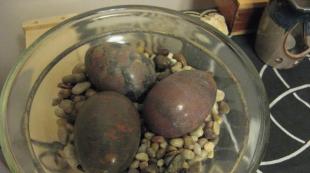
And this is what my sub looks like in a self-made case:

I tried to shoot a video, but the sound on the video is very bad for me. But still, I can say that from the phone at medium power it was already pecking so that the ears were wrapped, although the consumption of the entire circuit in working form was only about 10 watts (we multiply 14.3 by 0.73). In this example, I took the voltage, as in a car, that is, 14.4 Volts, which fits well into our operating range from 8 to 18 Volts.

If you do not have a powerful power source, then it can be assembled according to this scheme.
Do not go in cycles in this chip. These TDA chips, as I said, there are many types. Some of them amplify the stereo signal and can output sound to 4 speakers at once, as is done in car radios. So do not be lazy to rummage through the Internet and find a suitable TDA. After completing the assembly, let your neighbors check out your amplifier by unscrewing the volume knob for the entire balalaika and leaning the powerful speaker against the wall).
But in the article I assembled an amplifier on a TDA2030A chip

It turned out very well, since the TDA2030A has the best performance than TDA7396
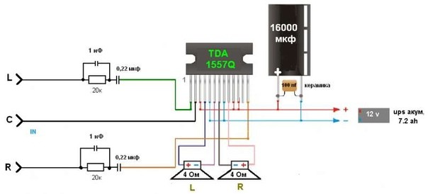
I will also add, for a change, another circuit from a subscriber whose amplifier on the TDA 1557Q has been working properly for more than 10 years in a row:
Amplifiers on Aliexpress
On Ali, I also found kit kits on TDA. For example, this stereo amplifier is 15 watts per channel and costs $1. This power is enough to hang out with your favorite tracks in the little room

You can buy.
But he's ready right now

Anyway, there are a lot of these amplifier modules on Aliexpress. Click on this link and choose any amplifier you like.
M. SAPozhnikov, Ganei Aviv, Israel
Radio, 2002, No. 4
The author proposes two simple two-way stereo UMZCH with a common low-frequency channel, which work with a personal computer in a multimedia system. The same amplifiers can also be used in a car radio complex or a portable music center.
In two-band or multi-band sound reproduction equipment, the separation of the bands is carried out by filters of the second, third and higher orders. But in simple stereo devices, it often makes sense to separate the bands at the output of the UMZCH stereo channels, which in this case should be wideband. The capacitor separating the UMZCH and the midrange - HF loudspeaker can be used as a low-pass filter element. In this case, the signal necessary for the operation of the low-frequency channel is formed directly on this capacitor. An increase in its reactance with a decrease in the frequency of the signal causes the same gradual increase in the voltage of the amplified signal across this capacitor. It is worth noting that broadband channels are not loaded at frequencies below the crossover frequency, and at these frequencies the distortion in the amplifier is much lower than with a broadband load. In addition, due to more efficient electro-acoustic conversion in dynamic heads in the MF - HF band, less power is required from the amplifier than for wideband heads.
On the circuit diagram(Fig. 1) shows two broadband UMZCH channels on the DA1 chip.
The heads of the midrange - HF acoustic system BA1 and BA2 with a common decoupling capacitor C6 are connected to the outputs of the microcircuit. large capacity. As a result, from the active resistances of the load VA1, VA2 and capacitor C6, a first-order low-pass filter is obtained. The signal of the low-frequency component is taken from it to the LF bridge amplifier, assembled on the DA2 chip.
The input circuits of the device consist of low-pass filters R1C1, R2C2, attenuating overtone and radio frequency interference, and a dual volume control R3.1, R3.2. At the input of the low-frequency channel, a sensitivity control R5 is installed to adjust the tonal balance of signals in the LF and MF - HF bands.
Microcircuits of the TDA1519 series were not chosen by chance. They provide good quality sound and at the same time have a minimum of attachments. The amplifier can be put into standby mode by switch SB1. It should be borne in mind that TDA1519Q microcircuits or without a letter index have two non-inverting amplifiers inside, they are installed in place of DA1, and in microcircuits with indices A and B one of the amplifiers is inverting, which is necessary for switching on the DA2 bridge circuit.
With a load of MF - HF channels with a resistance of 8 ohms and the specified supply voltage, the rated output power is about 2.5 W, and with a load of a LF channel with a resistance of 4 - 8 ohms - 9 ... 12 W with non-linear distortions of not more than 0.1%. When the capacitance of the capacitor C6 is about 220 μF, the band separation frequency is chosen to be about 180 Hz. Its value depends on the capacitance of this capacitor. If, however, a load with a resistance of 4 ohms is used in the MF - HF channels, then the power on it will double, but to maintain the crossover frequency, the capacitance of the capacitor C6 should be doubled. Amplification of broadband channels by voltage - 40 dB.
Instead of the TDA1519 (DA1) chip, it is permissible to use the TDA1517 chip. Then the gain of broadband channels will be equal to 20 dB.
Another UMZCH (Fig. 2) is based on the same principle of band separation in the load circuits of MF - HF channels, however, it uses TDA2005 microcircuits more familiar to many radio amateurs.

Click on the image to enlarge (opens in a new window)
Here, in broadband channels, current feedback through the load is used, which provides higher UMZCH parameters and allows you to have a signal on isolation capacitors (in this case there are two of them) that is identical to the input signal, with a level independent of the load impedance (of course, at frequencies below crossover frequency). The common LF channel is also assembled according to the bridge circuit, where both amplifiers of the DA2 chip are connected according to the inverse circuit. The R10 regulator, switched on by the rheostat, changes the signal gain in the bass channel.
The UMZCH parameters are approximately the same as in the previous device, but with a load resistance of 8 ohms, the voltage gain of the broadband amplifier is 26 dB and depends on the load resistance. If necessary, its sensitivity is changed by selecting resistors R6, R8. To select the capacitance of capacitors C12, C13, the same recommendations are suitable here as for C6 in the circuit shown in fig. one.
Both in the first and in the second amplifier, microcircuits must be installed on a heat sink with an effective area of at least 200 cm2. Printed circuit boards were not developed by the author; it is enough just to mount the amplifier elements on a suitable breadboard.
Having bought a good laptop or a cool phone, we are happy with the purchase, admiring the many features and speed of the device. But as soon as you connect the gadget to the speakers to listen to music or watch a movie, we understand that the sound produced by the device, as they say, “let us down”. Instead of a full and clear sound, we hear an unintelligible whisper with background noise.
But do not get upset and scold the manufacturers, you can solve the sound problem yourself. If you know a little about microcircuits and know how to solder well, then it will not be difficult for you to make your own audio amplifier. In our article, we will tell you how to make a sound amplifier for each type of device.
At the initial stage of work on creating an amplifier, you need to find tools and buy components. The amplifier circuit is made on printed circuit board with a soldering iron. To create chips, use special soldering stations that can be bought at the store. Using a printed circuit board allows you to make the device compact and easy to use.
 Audio frequency amplifier
 Do not forget about the features of compact single-channel amplifiers based on TDA series chips, the main of which is the generation of a large amount of heat. Therefore, try to internal arrangement amplifier, to exclude contact of the microcircuit with other parts. For additional cooling of the amplifier, it is recommended to use a radiator grill to remove heat. The size of the grating depends on the model of the microcircuit and the power of the amplifier. Plan in advance a place for a heat sink in the amplifier case.
Another feature self-manufacturing sound amplifier, is low power consumption. This, in turn, allows you to use the amplifier in the car by connecting it to the battery or on the road using battery power. Simplified amplifier models require a voltage of only 3 volts.
 The main elements of the amplifier
 If you are a beginner radio amateur, then for more convenient work, we recommend that you use a special computer program - Sprint Layout. With this program, you can create and view diagrams on your computer yourself. Please note that creating your own schema only makes sense if you have sufficient experience and knowledge. If you are an inexperienced radio amateur, then use ready-made and proven schemes.
Below we give diagrams and descriptions different options sound amplifier:
Headphone Amplifier
The portable headphone amplifier is not very powerful, but consumes very little power. This is an important factor for mobile amplifiers that are powered by batteries. You can also put a connector on the device for mains power through a 3 volt adapter.
 Homemade headphone amplifier
 To make a headphone amplifier you will need:
- Chip TDA2822 or equivalent KA2209.
- Amplifier assembly diagram.
- Capacitors 100uF 4 pieces.
- Headphone jack.
- Connector for adapter.
- Approximately 30 centimeters of copper wire.
- Heat sink element (for closed case).
 Headphone amplifier circuit
 The amplifier is made on a printed circuit board or surface-mounted. Do not use a pulse transformer in this type of amplifier, as it may cause interference. After manufacturing, this amplifier is able to provide a powerful and pleasant sound from a phone, player, or tablet.
You can see another version of a homemade headphone amplifier in the video:
Notebook sound amplifier
An amplifier for a laptop is assembled in cases where the power of the speakers built into it is not enough for normal listening, or if the speakers are out of order. The amplifier must be designed for external speakers up to 2 watts and winding resistance up to 4 ohms.
 Notebook sound amplifier
 To assemble the amplifier you will need:
- Printed circuit board.
- Chip TDA 7231.
- 9 volt power supply.
- Case for housing components.
- Capacitor non-polar 0.1 uF - 2 pieces.
- Capacitor polar 100 microfarad - 1 piece.
- Capacitor polar 220 microfarad - 1 piece.
- Capacitor polar 470 microfarad - 1 piece.
- Resistor constant 10 Kom - 1 piece.
- Resistor constant 4.7 Ohm - 1 piece.
- Two-position switch - 1 piece.
- Speaker input jack - 1 piece.
 Laptop Sound Amplifier Circuit
 The assembly order is determined independently depending on the scheme. The cooling radiator must be of such a size that the operating temperature inside the amplifier case does not exceed 50 degrees Celsius. If you plan to use the device outdoors, then you need to make a case for it with holes for air circulation. For the housing, you can use a plastic container or plastic boxes from old radio equipment.
You can see the visual instruction in the video:
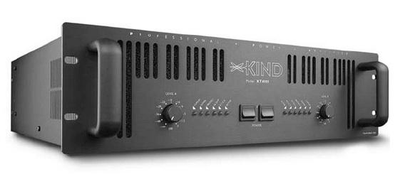
Sound amplifier for car radio
This amplifier for a car radio is assembled on a TDA8569Q chip, the circuit is not complicated and very common.
 Sound amplifier for car radio
 The microcircuit has the following declared characteristics:
- Input power 25 watts per channel into 4 ohms and 40 watts per channel into 2 ohms.
- Supply voltage 6-18 volts.
- The range of reproducible frequencies is 20-20000 Hz.
For use in a car, a filter must be added to the circuit from interference generated by the generator and ignition system. The microcircuit also has protection against short circuit at the output and overheating.
 Sound amplifier circuit for car radio
 Referring to the presented scheme, purchase the necessary components. Next, draw the PCB and drill holes in it. After that, etch the board with ferric chloride. In conclusion, we tinker and begin to solder the components of the microcircuit. Please note that it is better to cover the power tracks with a thicker layer of solder so that there are no power drawdowns.
You need to install a radiator on the microcircuit or organize active cooling using a cooler, otherwise the amplifier will overheat at high volume.
After assembling the microcircuit, it is necessary to make a filter for power supply according to the scheme below:
 Noise filter circuit
 The inductor in the filter is wound in 5 turns, with a wire with a cross section of 1-1.5 mm., On a ferite ring with a diameter of 20 mm.
Also, this filter can be used if your radio catches "pickup".
Attention! Be careful not to reverse the polarity of the power supply, otherwise the chip will burn out instantly.
How to make an amplifier for a stereo signal, you can also learn from the video:
Transistor audio amplifier
As a circuit for a transistor amplifier, use the circuit below:
 Transistor audio amplifier circuit
 The scheme, although old, has a lot of fans, for the following reasons:
- Simplified installation due to the small number of elements.
- There is no need to sort transistors into complementary pairs.
- 10 watts of power, with a margin enough for living rooms.
- Good compatibility with new sound cards and players.
- Excellent sound quality.
Start assembling the amplifier with power. Separate the two channels for stereo with two secondary windings coming from the same transformer. On the layout, make bridges on Schottky diodes for the rectifier. After the bridges, there are CRC filters of two 33,000 microfarad capacitors and a 0.75 ohm resistor between them. A powerful cement resistor is needed in the filter, with a quiescent current of up to 2A it will dissipate 3 W of heat, so it is better to take it with a margin of 5-10 W. For the rest of the resistors in the circuit, a power of 2 W will be enough.
 transistor amplifier
 Let's move on to the amplifier board. Everything except the output transistors Tr1/Tr2 is located on the board itself. The output transistors are mounted on heatsinks. It is better to put resistors R1, R2 and R6 first with trimmers, after all the adjustments, unsolder them, measure their resistance and solder the final fixed resistors with the same resistance. The setting comes down to the following operations - with the help of R6 it is set so that the voltage between X and zero is exactly half of the voltage + V and zero. Then, using R1 and R2, the quiescent current is set - we put the tester for measurement direct current and measure the current at the input point of the plus supply. The quiescent current of the amplifier in class A is maximum and, in fact, in the absence of an input signal, all goes into thermal energy. For 8 ohm speakers this should be 1.2 amps at 27 volts, which means 32.4 watts of heat per channel. Since it can take several minutes for the current to be set, the output transistors must already be on the cooling heatsinks, otherwise they will quickly overheat.
When adjusting and lowering the resistance of the amplifier, the cutoff frequency of the low frequencies may increase, so for the capacitor at the input it is better to use not 0.5 microfarads, but 1 or even 2 microfarads in a polymer film. It is believed that this circuit is not prone to self-excitation, but just in case, a Zobel circuit is placed between the X point and the ground: R 10 Ohm + C 0.1 microfarad. Fuses must be installed both on the transformer and on the power input of the circuit.
It's a good idea to use thermal paste to maximize contact between the transistor and the heatsink.
Now a few words about the body. The size of the case is set by radiators - NS135-250, 2500 square centimeters for each transistor. The body itself is made of plexiglass or plastic. Having assembled the amplifier, before you start enjoying the music, it is necessary to properly dilute the ground to minimize the background. To do this, connect the SZ to the minus of the input-output, and bring the remaining minuses to the "star" near the filter capacitors.
 Transistor audio amplifier housing
 approximate cost Supplies for transistor audio amplifier:
- Filter capacitors 4 pieces - 2700 rubles.
- Transformer - 2200 rubles.
- Radiators - 1800 rubles.
- Output transistors - 6-8 pieces 900 rubles.
- Small elements (resistors, capacitors, transistors, diodes) about - 2000 rubles.
- Connectors - 600 rubles.
- Plexiglas - 650 rubles.
- Paint - 250 rubles.
- Board, wires, solder about - 1000 rubles
The result is the amount - 12100 rubles.
You can also watch a video on assembling an amplifier based on germanium transistors:
Tube Sound Amplifier
A simple tube amplifier circuit consists of two stages - preamplifier on 6N23P and power amplifier on 6P14P.
 Tube amplifier circuit
 As can be seen from the diagram, both stages operate in a triode connection, and the anode current of the lamps is close to the limit. The currents are aligned with cathode resistors - 3mA for the input and 50mA for the output lamp.
The parts used for the tube amplifier must be new and of high quality. The permissible deviation of the resistor values can be plus or minus 20%, and the capacitances of all capacitors can be increased by 2-3 times.
Filter capacitors must be rated for at least 350 volts. The interstage capacitor must also be rated for the same voltage. Transformers for the amplifier can be ordinary - TV31-9 or a more modern analogue - TWSE-6.
 Tube Sound Amplifier
 It is better not to install the stereo volume and balance control on the amplifier, since these adjustments can be made in the computer or player itself. The input lamp is selected from - 6N1P, 6N2P, 6N23P, 6N3P. As an output pentode, 6P14P, 6P15P, 6P18P or 6P43P are used (with an increased resistance of the cathode resistor).
Even if you have a working transformer, it is better to use a conventional transformer with a 40-60 watt rectifier to turn on the paw amplifier for the first time. Only after a successful test and adjustment of the amplifier can a pulse transformer be installed.
Use standard sockets for plugs and cables; to connect speakers, it is better to install “pedals” on 4 pins.
The case for the paw amplifier is usually made from the shell of old equipment or cases of system units.
You can see another version of the tube amplifier in the video:
Classification of audio amplifiers
So that you can determine which class of sound amplifiers the device you have assembled belongs to, check out the UMZCH classification below:
 Class A Amplifier
 - Class A- amplifiers of this class operate without signal cutoff in the linear section of the current-voltage characteristic of amplifying elements, which ensures a minimum of non-linear distortions. But this comes at the cost of large amplifier size and huge power consumption. Class A amplifier efficiency is only 15-30%. This class includes tube and transistor amplifiers.
 Class B Amplifier
 - Class B- Class B amplifiers operate with a 90 degree cutoff signal. For the mode of such operation, a push-pull circuit is used, in which each part amplifies its half of the signal. The main disadvantage of class B amplifiers is signal distortion due to a stepwise transition from one half-wave to another. The advantage of this class of amplifiers is considered high efficiency sometimes reaching 70%. But despite the high performance, you will not find modern class B amplifier models on the shelves.
 Class AB Amplifier
 - Class AB- this is an attempt to combine amplifiers of the classes described above, in order to achieve the absence of signal distortion and high efficiency.
 Class H Amplifier
 - Class H- designed specifically for cars that have a voltage limit that feeds the output stages. The reason for the creation of class H amplifiers is that the real sound signal has a pulsed character and its average power is much lower than the peak. The circuit of this class of amplifiers is based on simple circuit for a class AB amplifier operating in a bridge circuit. Only a special scheme for doubling the supply voltage has been added. The main element of the doubling circuit is a large capacity storage capacitor, which is constantly charged from the main power source. At power peaks, this capacitor is connected by the control circuit to the main power supply. The power supply to the output stage of the amplifier is doubled, allowing it to cope with the transmission of signal peaks. The efficiency of class H amplifiers reaches 80%, with a signal distortion of only 0.1%.
 Class D Amplifier
 - Class D is a separate class of amplifiers called "digital amplifiers". Digital conversion provides additional possibilities for sound processing: from adjusting the volume and tone to the implementation of digital effects such as reverb, noise reduction, acoustic feedback suppression. Unlike analog amplifiers, class D amplifiers output a square wave. Their amplitude is constant, and the duration varies depending on the amplitude of the analog signal entering the amplifier input. The efficiency of amplifiers of this type can reach 90% -95%.
In conclusion, I would like to say that the occupation of radio electronics requires a large amount of knowledge and experience, which are acquired over a long period of time. Therefore, if something did not work out for you, do not be discouraged, reinforce your knowledge from other sources and try again!
In this article we will talk about amplifiers. They are ULF (low frequency amplifiers), they are also UMZCH (audio frequency power amplifiers). These devices can be made both on transistors and on microcircuits. Although some radio amateurs, paying tribute to vintage fashion, make them the old fashioned way - on lamps. Here we advise you to look. I want to pay special attention to beginners on microcircuits of automobile amplifiers with 12 volt power supply. Using them, you can get a fairly high-quality sound at the output, and for assembly, knowledge of a school physics course is practically enough. Sometimes from the body kit, or in other words, those parts on the diagram, without which the microcircuit will not work, there are literally 5 pieces on the diagram. One of these, an amplifier on a chip TDA1557Q shown in the figure:
Such an amplifier was assembled by me at one time, I have been using it for several years together with Soviet acoustics 8 Ohm 8 W, together with a computer. The sound quality is much higher than that of Chinese plastic speakers. True, to feel a significant difference, I had to buy a creative sound card, the difference was insignificant on the built-in sound.

The amplifier can be assembled by surface mounting
Also, the amplifier can be assembled by surface mounting, directly on the terminals of the parts, but I would not recommend assembling by this method. It is better to spend a little more time, find a printed circuit board (or breed it yourself), transfer the pattern to the textolite, etch it and end up with an amplifier that will work for many years. All these technologies have been described many times on the Internet, so I will not dwell on them in more detail.

Amplifier attached to the radiator
I must say right away that the amplifier microcircuits get very hot during operation and they must be fixed by applying thermal paste to the radiator. For those who just want to assemble one amplifier and do not have the time or desire to study PCB layout programs, LUT technologies and etching, I can suggest using special prototyping boards with solder holes. One of them is shown in the photo below:

As you can see in the photo, the connections are not made by tracks on the printed circuit board, as is the case with printed wiring, but by flexible wires soldered to the contacts on the board. The only problem when assembling such amplifiers is the power supply, which produces a voltage of 12-16 volts, with a current consumption of up to 5 amperes by the amplifier. Of course, such a transformer (for 5 amperes) will be rather large, so some use pulsed sources nutrition.
![]()
Transformer for amplifier - photo
Many, I think, have computer power supplies at home that are now obsolete and are no longer used as part of system units, and so such power supplies are capable of delivering +12 volts through circuits, currents much larger than 4 amperes. Of course, such a power supply among connoisseurs of sound is considered worse than a standard transformer one, but I connected a switching power supply to power my amplifier, then changed it to a transformer one - the difference in sound can be said to be imperceptible.

After leaving the transformer, of course, you need to put a diode bridge to rectify the current, which must be designed to work with high currents consumed by the amplifier.

After the diode bridge there is a filter on an electrolytic capacitor, which must be designed for a noticeably higher voltage than we have in the circuit. For example, if we have 16 volts in the circuit, the capacitor should be 25 volts. Moreover, this capacitor should be as large as possible, I have 2 2200 microfarad capacitors connected in parallel, and this is not the limit. In parallel with the power supply (shunt), you need to connect a ceramic capacitor with a capacity of 100 nF. At the input of the amplifier, film coupling capacitors are placed with a capacity of 0.22 to 1 microfarad.

Film Capacitors
The connection of the signal to the amplifier, in order to reduce the level of induced interference, should be carried out with a shielded cable, for these purposes it is convenient to use a cable Jack 3.5- 2 Tulips, with corresponding sockets on the amplifier.

Jack cable 3.5 - 2 tulips
The signal level (the volume on the amplifier) is adjusted using a potentiometer, if the amplifier is stereo, then dual. The connection diagram of the variable resistor is shown in the figure below:

Of course, amplifiers can also be made on transistors, while power, connection and volume control are used in them in the same way as in amplifiers on microcircuits. Consider, for example, a single-transistor amplifier circuit:

There is also a decoupling capacitor, and the minus of the signal is connected to the minus of the power supply. Below is a diagram of a push-pull power amplifier with two transistors:

The following circuit is also on two transistors, but assembled from two stages. Indeed, if you look closely, it seems to consist of 2 almost identical parts. Our first cascade includes: C1, R1, R2, V1. In the second stage C2, R3, V2, and load headphones B1.

Two-stage transistor amplifier - circuit
If we want to make a stereo amplifier, we will need to assemble two identical channels. In the same way, we can, by assembling two circuits of any mono amplifier, turn it into stereo. Below is a diagram of a three-stage transistorized power amplifier:

Three-stage transistor amplifier - circuit
Amplifier circuits also differ in supply voltage, some need 3-5 volts to operate, others need 20 or more. Some amplifiers require bipolar power to operate. The following are 2 amplifier circuits on a chip TDA2822, the first stereo connection:

In the diagram, in the form of resistors RL, the speaker connections are indicated. The amplifier normally operates on a voltage of 4 volts. The following figure shows a bridged circuit that uses a single speaker but delivers more power than the stereo version:

The following figure shows the amplifier circuits on, both circuits are taken from the datasheet. Power supply 18 volts, power 14 watts:


The acoustics connected to the amplifier can have different impedance, most often it is 4-8 ohms, sometimes there are speakers with a resistance of 16 ohms. You can find out the resistance of the speaker by turning it with its back to you, the nominal power and resistance of the speaker are usually written there. In our case, this is 8 ohms, 15 watts.

If the speaker is inside the column and there is no way to see what is written on it, then the speaker can be called by the tester in ohmmeter mode by selecting the measurement limit of 200 ohms.

Speakers are polarized. The cables with which the acoustics are connected are usually marked in red, for the wire that is connected to the plus of the speaker.

If the wires are not marked, you can check the correct connection by connecting the battery plus to plus, minus to speaker minus (conditionally), if the speaker cone extends outward, then we guessed with the polarity. More various ULF circuits, including tube ones, can be found at. It contains, we think, the largest selection of schemes on the Internet.
At some point, I finally got tired of the weak sound from plastic 10-watt computer speakers and I wanted really high power, and of course better bass! Buying active speakers 100 watts is not a problem - the problem is finding 10,000 rubles for such a thing. But you can get by with a sum 10 times less if you assemble the electronics yourself, and find passive speakers of suitable power.
Electrical diagram UMZCH
The electronics of computer speakers consists of several systems:
- The tip is a sound power amplifier for 2 x TDA7294.
- Preamplifier on the TL072 chip.
- Signal input selector with touch button and CD4017 + relay.
- The bluetooth module from the Chinese set.
- Switching on / off using the same touch button on CD4017 + relay
- Cooling system with thermal control on the field MOSFET.
 Wiring diagram 2хtda7294
  PCB drawing
 Here we give only the most basic circuit - a stereo bass amplifier block. The rest of the modules have no features and are made according to standard schemes, which are not a problem to find. Or exclude it altogether, since the main thing is the amplifier itself on the TDA7294.
 Homemade homemade UMZCH
 Amplifier housing
The case was created from board and MDF. In general, the design of this amplifier is a problem for those who want to perform mechanical work at home - not easy to find the right materials and equipment. But if you weren’t lucky enough to find a suitable box, then we think it’s not a problem for anyone to put it together from MDF.
 Case ULF 2x100 W
 ULF tests at home
A subwoofer is not needed here - with good power and large woofers in the lower-end speakers, it will be more than enough. As a result, with this design, we managed to get 2 x 60 watts of power, and this is not at the limit (so that there is less distortion). So everyone is happy with the sound, including the neighbors!