DIY deep metal detector. How to make a metal detector with your own hands - cost-effective and proven schemes Manual metal detector diagram
BEST METAL DETECTOR
Why was Volksturm named the best metal detector? The main thing is that the scheme is really simple and really working. Of the many metal detector circuits that I have personally made, this is the one where everything is simple, thorough and reliable! Moreover, despite its simplicity, the metal detector has a good discrimination scheme - determining whether iron or non-ferrous metal is in the ground. Assembling the metal detector consists of error-free soldering of the board and setting the coils to resonance and to zero at the output of the input stage on the LF353. There is nothing super complicated here, all you need is desire and brains. Let's look at the constructive metal detector design and a new improved Volksturm diagram with description.
Since questions arise during the assembly process, in order to save you time and not force you to flip through hundreds of forum pages, here are the answers to the 10 most popular questions. The article is in the process of being written, so some points will be added later.
1. The operating principle and target detection of this metal detector?
2. How to check if the metal detector board is working?
3. Which resonance should I choose?
4. Which capacitors are better?
5. How to adjust resonance?
6. How to reset the coils to zero?
7. Which wire is better for coils?
8. What parts can be replaced and with what?
9. What determines the depth of target search?
10. Volksturm metal detector power supply?
How the Volksturm metal detector works
I will try to briefly describe the principle of operation: transmission, reception and induction balance. In the search sensor of the metal detector, 2 coils are installed - transmitting and receiving. The presence of metal changes the inductive coupling between them (including the phase), which affects the received signal, which is then processed by the display unit. Between the first and second microcircuits there is a switch controlled by pulses of a generator phase-shifted relative to the transmitting channel (i.e. when the transmitter is working, the receiver is turned off and vice versa, if the receiver is turned on, the transmitter is resting, and the receiver calmly catches the reflected signal in this pause). So, you turned on the metal detector and it beeps. Great, if it beeps, it means many nodes are working. Let's figure out why exactly it beeps. The generator on the u6B constantly generates a tone signal. Next, it goes to an amplifier with two transistors, but the amplifier will not open (it will not let a tone pass) until the voltage at the output u2B (7th pin) allows it to do so. This voltage is set by changing the mode using this same thrash resistor. They need to set the voltage so that the amplifier almost opens and passes the signal from the generator. And the input couple of millivolts from the metal detector coil, having passed through the amplification stages, will exceed this threshold and it will finally open and the speaker will beep. Now let's trace the passage of the signal, or rather the response signal. At the first stage (1-у1а) there will be a couple of millivolts, up to 50. At the second stage (7-у1B) this deviation will increase, at the third (1-у2А) there will already be a couple of volts. But there is no response everywhere at the outputs.
How to check if the metal detector board is working

In general, the amplifier and switch (CD 4066) are checked with a finger at the RX input contact at maximum sensor resistance and maximum background on the speaker. If there is a change in the background when you press your finger for a second, then the key and opamps work, then we connect the RX coils with the circuit capacitor in parallel, the capacitor on the TX coil in series, put one coil on top of the other and begin to reduce to 0 according to the minimum reading of the alternating current on the first leg of the amplifier U1A. Next, we take something large and iron and check whether there is a reaction to metal in the dynamics or not. Let's check the voltage at y2B (7th pin), it should change with a thrash regulator + a couple of volts. If not, the problem is in this op-amp stage. To start checking the board, turn off the coils and turn on the power.
1. There should be a sound when the sense regulator is set to maximum resistance, touch the RX with your finger - if there is a reaction, all op-amps work, if not, check with your finger starting from u2 and change (inspect the wiring) of the non-working op-amp.
2. The operation of the generator is checked by the frequency meter program. Solder the headphone plug to pin 12 of the CD4013 (561TM2), carefully removing p23 (so as not to burn the sound card). Use In-lane on the sound card. We look at the generation frequency and its stability at 8192 Hz. If it is strongly shifted, then it is necessary to unsolder the capacitor c9, if even after it is not clearly identified and/or there are many frequency bursts nearby, we replace the quartz.
3. Checked the amplifiers and generator. If everything is in order, but still does not work, change the key (CD 4066).
Which coil resonance to choose?

When connecting the coil into series resonance, the current in the coil and the overall consumption of the circuit increases. The target detection distance increases, but this is only on the table. On real ground, the ground will be felt the more strongly, the greater the pump current in the coil. It is better to turn on parallel resonance, and increase the sense of input stages. And the batteries will last much longer. Despite the fact that sequential resonance is used in all branded expensive metal detectors, in Sturm it is parallel that is needed. In imported, expensive devices, there is a good detuning circuitry from the ground, so in these devices it is possible to allow sequential.
Which capacitors are best installed in the circuit? metal detector

The type of capacitor connected to the coil has nothing to do with it, but if you experimentally changed two and saw that with one of them the resonance is better, then simply one of the supposedly 0.1 μF actually has 0.098 μF, and the other 0.11. This is the difference between them in terms of resonance. I used Soviet K73-17 and green imported pillows.
How to adjust coil resonance metal detector

The coil, as the best option, is made from plaster floats, glued with epoxy resin from the ends to the size you need. Moreover, its central part contains a piece of the handle of this very grater, which is processed down to one wide ear. On the bar, on the contrary, there is a fork with two mounting ears. This solution allows us to solve the problem of coil deformation when tightening the plastic bolt. The grooves for the windings are made with a regular burner, then zero is set and filled. From the cold end of the TX, leave 50 cm of wire, which should not be filled initially, but make a small coil from it (3 cm in diameter) and place it inside the RX, moving and deforming it within small limits, you can achieve an exact zero, but do this It’s better outside, placing the coil near the ground (as when searching) with GEB turned off, if any, then finally fill it with resin. Then the detuning from the ground works more or less tolerably (with the exception of highly mineralized soil). Such a reel turns out to be light, durable, little subject to thermal deformation, and when processed and painted it is very attractive. And one more observation: if the metal detector is assembled with ground detuning (GEB) and with the resistor slider located centrally, set zero with a very small washer, the GEB adjustment range is + - 80-100 mV. If you set zero with a large object - a coin of 10-50 kopecks. the adjustment range increases to +- 500-600 mV. Do not chase the voltage when setting up the resonance - with a 12V supply, I have about 40V with a series resonance. To make discrimination appear, we connect the capacitors in the coils in parallel (series connection is only necessary at the stage of selecting capacitors for resonance) - for ferrous metals there will be a drawn-out sound, for non-ferrous metals - a short one.
Or even simpler. We connect the coils one by one to the transmitting TX output. We tune one into resonance, and after tuning it, the other. Step by step: Connected, poked a multimeter in parallel with the coil with a multimeter at the alternating volts limit, also soldered a 0.07-0.08 uF capacitor parallel to the coil, look at the readings. Let's say 4 V - very weak, not in resonance with the frequency. We poked a second small capacitor in parallel with the first capacitor - 0.01 microfarads (0.07+0.01=0.08). Let's look - the voltmeter has already shown 7 V. Great, let's increase the capacitance further, connect it to 0.02 µF - look at the voltmeter, and there is 20 V. Great, let's move on - we'll add a couple thousand more peak capacitance. Yeah. It has already started to fall, let's roll back. And so achieve maximum voltmeter readings on the metal detector coil. Then do the same with the other (receiving) coil. Adjust to maximum and connect back to the receiving socket.
How to zero metal detector coils

To adjust the zero, we connect the tester to the first leg of the LF353 and gradually begin to compress and stretch the coil. After filling with epoxy, the zero will definitely run away. Therefore, it is necessary not to fill the entire coil, but to leave places for adjustment, and after drying, bring it to zero and fill it completely. Take a piece of twine and tie half of the spool with one turn to the middle (to the central part, the junction of the two spools), insert a piece of stick into the loop of the twine and then twist it (pull the twine) - the spool will shrink, catching the zero, soak the twine in glue, after almost complete drying adjust the zero again by turning the stick a little more and fill the twine completely. Or simpler: The transmitting one is fixed in plastic, and the receiving one is placed 1 cm over the first one, like wedding rings. There will be an 8 kHz squeak at the first pin of U1A - you can monitor it with an AC voltmeter, but it’s better to just use high-impedance headphones. So, the receiving coil of the metal detector must be moved or shifted from the transmitting coil until the squeak at the output of the op-amp subsides to a minimum (or the voltmeter readings drop to several millivolts). That's it, the coil is closed, we fix it.
Which wire is better for search coils?

The wire for winding the coils does not matter. Anything from 0.3 to 0.8 will do; you still have to slightly select the capacitance to tune the circuits to resonance and at a frequency of 8.192 kHz. Of course, a thinner wire is quite suitable, it’s just that the thicker it is, the better the quality factor and, as a result, the instinct. But if you wind it 1 mm, it will be quite heavy to carry. On a sheet of paper, draw a rectangle 15 by 23 cm. From the upper and lower left corners, set aside 2.5 cm and connect them with a line. We do the same with the upper right and lower corners, but set aside 3 cm each. We put a dot in the middle of the lower part and a point on the left and right at a distance of 1 cm. We take plywood, apply this sketch and drive nails into all the points indicated. We take a PEV 0.3 wire and wind 80 turns of wire. But honestly, it doesn’t matter how many turns. Anyway, we will set the frequency of 8 kHz to resonance with a capacitor. As much as they reeled in, that's how much they reeled in. I wound 80 turns and a capacitor of 0.1 microfarads, if you wind it, say 50, you will have to put a capacitance of about 0.13 microfarads. Next, without removing it from the template, we wrap the coil with a thick thread - like how wire harnesses are wrapped. Afterwards we coat the coil with varnish. When dry, remove the spool from the template. Then the coil is wrapped with insulation - fum tape or electrical tape. Next - winding the receiving coil with foil, you can take a tape from electrolytic capacitors. The TX coil does not need to be shielded. Remember to leave a 10mm GAP in the screen, down the middle of the reel. Next comes winding the foil with tinned wire. This wire, together with the initial contact of the coil, will be our ground. And finally, wrap the coil with electrical tape. The inductance of the coils is about 3.5mH. The capacitance turns out to be about 0.1 microfarads. As for filling the coil with epoxy, I didn’t fill it at all. I just wrapped it tightly with electrical tape. And nothing, I spent two seasons with this metal detector without changing the settings. Pay attention to the moisture insulation of the circuit and search coils, because you will have to mow on wet grass. Everything must be sealed - otherwise moisture will get in and the setting will float. Sensitivity will worsen.
What parts can be replaced and with what?

Transistors:
BC546 - 3pcs or KT315.
BC556 - 1 piece or KT361
Operators:
LF353 - 1 piece or exchange for the more common TL072.
LM358N - 2pcs
Digital chips:
CD4011 - 1 piece
CD4066 - 1 piece
CD4013 - 1 piece
Resistors are constant, power 0.125-0.25 W:
5.6K - 1 piece
430K - 1 piece
22K - 3pcs
10K - 1 piece
390K - 1 piece
1K - 2pcs
1.5K - 1 piece
100K - 8pcs
220K - 1 piece
130K - 2 pieces
56K - 1 piece
8.2K - 1 piece
Variable resistors:
100K - 1 piece
330K - 1 piece
Non-polar capacitors:
1nF - 1 piece
22nF - 3pcs (22000pF = 22nF = 0.022uF)
220nF - 1 piece
1uF - 2pcs
47nF - 1 piece
10nF - 1 piece
Electrolytic capacitors:
220uF at 16V - 2 pcs
The speaker is miniature.
Quartz resonator at 32768 Hz.
Two ultra-bright LEDs of different colors.
If you cannot get imported microcircuits, here are domestic analogues: CD 4066 - K561KT3, CD4013 - 561TM2, CD4011 - 561LA7, LM358N - KR1040UD1. The LF353 microcircuit has no direct analogue, but feel free to install LM358N or better TL072, TL062. It is not at all necessary to install an operational amplifier - LF353, I simply increased the gain to U1A by replacing the resistor in the negative feedback circuit of 390 kOhm with 1 mOhm - the sensitivity increased significantly by 50 percent, although after this replacement the zero went away, I had to glue it to the coil in a certain place tape a piece of aluminum plate. Soviet three kopecks can be sensed through the air at a distance of 25 centimeters, and this is with a 6-volt power supply, the current consumption without indication is 10 mA. And don’t forget about the sockets - the convenience and ease of setup will increase significantly. Transistors KT814, Kt815 - in the transmitting part of the metal detector, KT315 in the ULF. It is advisable to select transistors 816 and 817 with the same gain. Replaceable with any corresponding structure and power. The metal detector generator has a special clock quartz at a frequency of 32768 Hz. This is the standard for absolutely all quartz resonators found in any electronic and electromechanical watches. Including wrist and cheap Chinese wall/table ones. Archives with a printed circuit board for the variant and for (variant with manual detuning from the ground).
What determines the depth of target search?
The larger the diameter of the metal detector coil, the deeper the instinct. In general, the depth of target detection by a given coil depends primarily on the size of the target itself. But as the diameter of the coil increases, there is a decrease in the accuracy of object detection and sometimes even the loss of small targets. For objects the size of a coin, this effect is observed when the coil size increases above 40 cm. Overall: a large search coil has a greater detection depth and greater capture, but detects the target less accurately than a small one. The large coil is ideal for searching for deep and large targets such as treasure and large objects.
According to their shape, coils are divided into round and elliptical (rectangular). An elliptical metal detector coil has better selectivity compared to a round one, because the width of its magnetic field is smaller and fewer foreign objects fall into its field of action. But the round one has a greater detection depth and better sensitivity to the target. Especially on weakly mineralized soils. The round coil is most often used when searching with a metal detector.
Coils with a diameter of less than 15 cm are called small, coils with a diameter of 15-30 cm are called medium, and coils over 30 cm are called large. A large coil generates a larger electromagnetic field, so it has a greater detection depth than a small one. Large coils generate a large electromagnetic field and, accordingly, have greater detection depth and search coverage. Such coils are used to view large areas, but when using them, a problem may arise in heavily littered areas because several targets may be caught in the field of action of large coils at once and the metal detector will react to a larger target.
The electromagnetic field of a small search coil is also small, so with such a coil it is best to search in areas heavily littered with all sorts of small metal objects. The small coil is ideal for detecting small objects, but has a small coverage area and a relatively shallow detection depth.
For universal searching, medium coils are well suited. This search coil size combines sufficient search depth and sensitivity to targets of different sizes. I made each coil with a diameter of approximately 16 cm and placed both of these coils in a round stand from under an old 15" monitor. In this version, the search depth of this metal detector will be as follows: aluminum plate 50x70 mm - 60 cm, nut M5-5 cm, coin - 30 cm, bucket - about a meter. These values were obtained in the air, in the ground it will be 30% less.
Metal detector power supply
Separately, the metal detector circuit draws 15-20 mA, with the coil connected + 30-40 mA, totaling up to 60 mA. Of course, depending on the type of speaker and LEDs used, this value may vary. The simplest case is that the power was taken from 3 (or even two) lithium-ion batteries connected in series from a 3.7V mobile phone and when charging discharged batteries, when we connect any 12-13V power supply, the charging current starts from 0.8A and drops to 50mA per an hour and then you don’t need to add anything at all, although a limiting resistor certainly wouldn’t hurt. In general, the simplest option is a 9V crown. But keep in mind that the metal detector will eat it in 2 hours. But for customization, this power option is just right. Under any circumstances, the crown will not produce a large current that could burn something on the board.
Homemade metal detector

And now a description of the process of assembling a metal detector from one of the visitors. Since the only instrument I have is a multimeter, I downloaded O.L. Zapisnykh’s virtual laboratory from the Internet. I assembled an adapter, a simple generator and ran the oscilloscope at idle. It seems to show some kind of picture. Then I started looking for radio components. Since signets are mostly laid out in the “lay” format, I downloaded “Sprint-Layout50”. I found out what laser-iron technology is for manufacturing printed circuit boards and how to etch them. Etched the board. By this time, all the microcircuits had been found. Whatever I couldn’t find in my shed, I had to buy. I started soldering jumpers, resistors, microcircuit sockets, and quartz from a Chinese alarm clock onto the board. Periodically checking the resistance on the power buses to ensure there are no snot. I decided to start by assembling the digital part of the device, as it would be the easiest. That is, a generator, a divider and a commutator. Collected. I installed a generator chip (K561LA7) and a divider (K561TM2). Used ear chips, torn out from some circuit boards found in a shed. I applied 12V power while monitoring the current consumption using an ammeter, and the 561TM2 became warm. Replaced 561TM2, applied power - zero emotions. I measure the voltage on the generator legs - 12V on legs 1 and 2. I am changing 561LA7. I turn it on - at the output of the divider, on the 13th leg there is generation (I observe it on a virtual oscilloscope)! The picture is really not that great, but in the absence of a normal oscilloscope it will do. But there is nothing on legs 1, 2 and 12. This means the generator is working, you need to change TM2. I installed a third divider chip - there is beauty on all outputs! I came to the conclusion that you need to desolder the microcircuits as carefully as possible! This completes the first step of construction.
Now we set up the metal detector board. The "SENS" sensitivity regulator did not work, I had to throw out the capacitor C3 after that the sensitivity adjustment worked as it should. I didn’t like the sound that appeared in the extreme left position of the “THRESH” regulator - threshold, I got rid of it by replacing resistor R9 with a chain of series-connected 5.6 kOhm resistor + 47.0 μF capacitor (negative terminal of the capacitor on the transistor side). While there is no LF353 microcircuit, I installed the LM358 instead; with it, Soviet three kopecks can be sensed in the air at a distance of 15 centimeters.

I turned on the search coil for transmission as a series oscillatory circuit, and for reception as a parallel oscillatory circuit. I set up the transmitting coil first, connected the assembled sensor structure to the metal detector, an oscilloscope parallel to the coil, and selected capacitors based on the maximum amplitude. After this, I connected the oscilloscope to the receiving coil and selected the capacitors for RX based on the maximum amplitude. Setting the circuits to resonance takes several minutes if you have an oscilloscope. My TX and RX windings each contain 100 turns of wire with a diameter of 0.4. We start mixing on the table, without the body. Just to have two hoops with wires. And to make sure of the functionality and possibility of mixing in general, we will separate the coils from each other by half a meter. Then it will be zero for sure. Then, having overlapped the coils by about 1 cm (like wedding rings), move and push apart. The zero point can be quite accurate and it is not easy to catch it right away. But it is there.

When I raised the gain in the RX path of the MD, it began to work unstably at maximum sensitivity, this was manifested in the fact that after passing over the target and detecting it, a signal was issued, but it continued even after there was no target in front of the search coil, this manifested itself in the form of intermittent and fluctuating sound signals. Using an oscilloscope, the reason for this was discovered: when the speaker is operating and the supply voltage drops slightly, “zero” goes away and the MD circuit goes into a self-oscillating mode, which can only be exited by coarsening the sound signal threshold. This didn’t suit me, so I installed a KR142EN5A + super bright white LED for power supply to raise the voltage at the output of the integrated stabilizer; I didn’t have a stabilizer for a higher voltage. This LED can even be used to illuminate the search coil. I connected the speaker to the stabilizer, after that the MD immediately became very obedient, everything started working as it should. I think the Volksturm is truly the best homemade metal detector!
Recently, this modification scheme was proposed, which would turn the Volksturm S into the Volksturm SS + GEB. Now the device will have a good discriminator as well as metal selectivity and ground detuning; the device is soldered on a separate board and connected instead of capacitors C5 and C4. The revision scheme is also in the archive. Special thanks for the information on assembling and setting up the metal detector to everyone who took part in the discussion and modernization of the circuit; Elektrodych, fez, xxx, slavake, ew2bw, redkii and other fellow radio amateurs especially helped in preparing the material.
Anyone can assemble such a device, even those who are completely far from electronics, you just need to solder all the parts as in the diagram. The metal detector consists of two microcircuits. They do not require any firmware or programming.
Power supply is 12 volts, you can use AA batteries, but it’s better to use a 12V battery (small)
The coil is wound on a 190mm mandrel and contains 25 turns of PEV 0.5 wire
Characteristics:
- Current consumption 30-40 mA
- Reacts to all metals, no discrimination
- Sensitivity 25 mm coin - 20 cm
- Large metal objects - 150 cm
- All parts are inexpensive and easily accessible.
List of required parts:
1) Soldering iron
2) Textolite
3) Wires
4) Drill 1mm
Here is a list of required parts

Diagram of the metal detector itself

The circuit uses 2 microcircuits (NE555 and K157UD2). They are quite common. K157UD2 - can be picked out from old equipment, which I did with success


Be sure to take 100nF film capacitors, like these, take the voltage as low as possible

Print out the board sketch on plain paper

We cut a piece of textolite to its size.

We apply it tightly and press it with a sharp object in the places of future holes.

This is how it should turn out.

Next, take any drill or drilling machine and drill holes


After drilling, you need to draw tracks. You can do this through, or simply paint them with Nitro varnish with a simple brush. The tracks should look exactly the same as on the paper template. And we poison the board.

In the places marked in red, place jumpers:


Next, we simply solder all the components into place.
For K157UD2 it is better to install an adapter socket.


To wind the search coil you need a copper wire with a diameter of 0.5-0.7 mm

If there is none, you can use another one. I didn’t have enough varnished copper wire. I took an old network cable.

He took off the shell. There were enough wires there. Two cores were enough for me, and they were used to wind the coil.


According to the diagram, the coil has a diameter of 19 cm and contains 25 turns. I’ll immediately note that the coil needs to be made of such a diameter based on what you will be looking for. The larger the coil, the deeper the search, but a large coil does not see small details well. The small coil sees small details well, but the depth is not great. I immediately wound three coils of 23cm (25 turns), 15cm (17 turns) and 10cm (13-15 turns). If you need to dig up scrap metal, then use a large one; if you are looking for small things on the beach, then use a smaller reel, but you’ll figure it out for yourself.
We wind the coil on anything of a suitable diameter and wrap it tightly with electrical tape so that the turns are tightly next to each other.


The coil should be as level as possible. The speaker took the first one available.
Now we connect everything and test the circuit to see if it works.
After applying power, you need to wait 15-20 seconds until the circuit warms up. We place the coil away from any metal, it is best to hang it in the air. Then we begin to twist the 100K variable resistor until clicks appear. As soon as the clicks appear, turn it in the opposite direction; as soon as the clicks disappear, that’s enough. After this, we also adjust the 10K resistor.
Regarding the K157UD2 microcircuit. In addition to the one I picked out, I asked one more from a neighbor and bought two at the radio market. I inserted the purchased microcircuits, turned on the device, but it refused to work. I racked my brains for a long time until I simply installed another microcircuit (the one I removed). And everything started working right away. So this is why you need an adapter socket, so that you can select a live microcircuit and not have to worry about desoldering and soldering.
Purchased chips
A metal detector is used to search for small metal objects in the soil. But a store-bought product of this kind is quite expensive. To assemble it yourself, it is enough to know the principle of its operation and have a little understanding of electrical engineering.
At the same time, the simplest scheme does not allow determining the type of metal; the discrimination function, in other words, determining the type of find, somewhat complicates the design of the metal detector, but at the same time significantly expands the owner’s capabilities when searching.
To assemble a metal detector with metal discrimination with your own hands, you need to have basic knowledge and be able to work with a soldering iron. The cost of a self-assembled device will be lower than that of a factory-made analogue.
General structure of the metal detector
Metal detectors generally operate on the principle of electromagnetic induction. The transmitting coil generates electromagnetic radiation that penetrates the ground. Reception - receives signals from metal objects located in the ground. Often the functions of both coils are combined into one - a transceiver search coil. The control circuit generates an audible signal indicating that a metal object has entered the search zone; in addition, a visual indicator in the form of a lamp or LCD panel can be used.
Metal detectors are usually assembled according to a classical design and consist of the following main parts:
- search transceiver coil;
- generator of electromagnetic radiation;
- vibration receiver;
- decoder, whose task is to isolate the noise background of an object from the general noise;
- rods on which the equipment is fixed;
- indicator system: sound and visual signaling device.
All elements of the search structure are placed on a bar; the length of the bar is selected based on the anatomical characteristics of the owner.
A discriminator, in other words, a determinant, based on the properties of the object’s material, is usually built into the control circuit; its task is to more accurately determine the characteristics of the find based on disturbances in the electromagnetic field.

Operating principle
The generator creates an electromagnetic field with predetermined characteristics around the search coil. The shape of the field and its depth depend both on the characteristics of the generator and on the shape of the coil itself.
When searching, if there are no disturbances in the electromagnetic field, nothing happens. But when a conductive object enters the electromagnetic field zone, it creates Foucault currents. When a disturbance hits the receiver, it must determine the approximate type of object and transmit information about it to the alarm device. The same story happens when an object with ferromagnetic properties appears in the search field. The characteristics of the soil affect the search field, but at the same time, with the correct settings of the characteristics of the metal detector, more precisely the radiation parameters, this interference can be minimized.
Important! Metal discrimination is one of the functions of a metal detector, which allows you to determine which category a find belongs to. It works by separating the material of an object according to the conductivity of electromagnetic waves. This will eliminate various debris and ferrous metals from the search area.
Self-assembly of a metal detector
There are several working circuits of a metal detector intended for self-assembly: from the simplest “Pirate” type to the more complex “Chance” type, with metal discrimination. The latter is worth talking about in more detail.
The main thing in any metal detector is the coil. You can use either a factory-made coil from a store or make it yourself. To work, you will need copper winding wire 0.67-0.82.
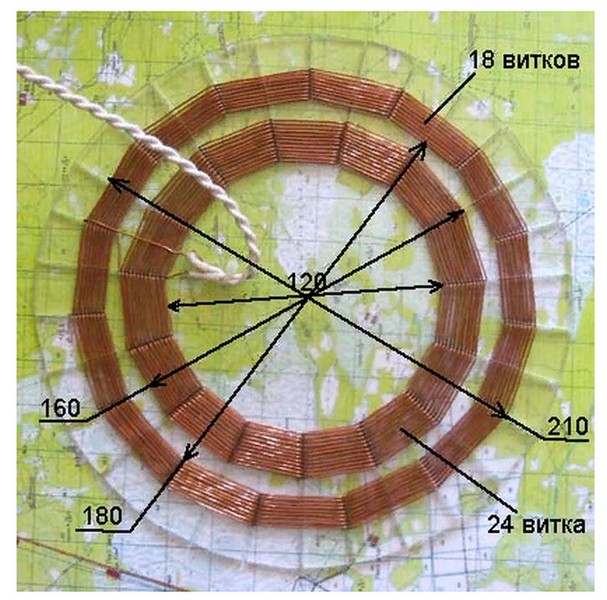
You can make a simple coil of 90 turns of winding wire for a 100-1200 mm mandrel, but with such a coil design, discrimination will not work correctly. Therefore, it is proposed to assemble a search coil from two windings: an external one with a diameter of 210 mm from 18 turns and an internal one with a diameter of 160 from 24 turns. For ease of manufacture, marking and winding of contours should be done on a plate made of non-magnetic material, for example, plexiglass or thick cardboard.
In addition, it is worth sealing the winding; for this you can use any non-magnetic materials, this will increase the resistance of the metal of the product to moisture.
We'll take the metal detector control unit from Andrey Fedorov. This scheme has already proven itself on the positive side and has been tested many times.
The printed circuit board can also be made independently: from textolite, with a foil pattern applied using the materials provided below. Usually, skills in working with printed circuit boards are sufficient for this. Drawing conductive paths according to a pre-made sketch is a fairly simple process. An iron or a hair dryer is sufficient for this purpose.
Its base is a microprocessor of the ATmega8 type, with a converter of the MCP3201 type. A microcontroller of this type is quite scarce, but despite this, it is sold in a number of online stores. Finding it and purchasing other components will not cause any special problems. Soldering of the control panel is carried out according to the diagram below.

When soldering, you need to carefully monitor the placement of parts and elements on the board. The circuit is quite complex, and the failure of one or two elements will throw all the work down the drain. Don't forget about safety precautions when soldering.
Important! It is worth clarifying that the circuit uses an ICL7660S voltage converter; the letter S indicates that this converter operates with voltages up to 12V. This is what you need to use; when using the ICL7660, the converter may fail due to overheating.
You can download a drawing of the printed circuit board and a full description of the assembly from this link www.miriskateley.com/.
Materials and equipment
To make a coil, a winding wire with a diameter of 0.6-0.8 mm is used; when winding, you need to carefully monitor its condition to prevent damage to the enamel coating. The base is a circle made of non-magnetic, electrically permeable material with a diameter of at least 250 mm.
A complete list of materials used and the possibilities of replacing them with analogues
| Detail | Analogue | Quantity |
|---|---|---|
| NE5534 | 1 | |
| Converter MCP3201 | 1 | |
| ICL7660s converter | 1 | |
| ATMega8 controller | 1 | |
| Zener diode TL431 | 1 | |
| Voltage stabilizer 78l05 | 1 | |
| Quartz at 11.0592 MHz | 1 | |
| Diodes 1N4148 | KD522 | 10 |
| Diode 1N5819 | KD510 | 1 |
| Diodes HER208 | HER207 | 2 |
| Transistors 2SC945 | 5 | |
| Transistors IRF9640 | 2 | |
| Transistors A733 | 2SA733 | 2 |
| Capacitors, ceramics | 13 | |
| Electrolytic capacitors of different ratings | 8 | |
| Resistors | 27 | |
| Buttons art. SWT5 | 6 | |
| LCD QC1602A | 1 |
Programming the control unit
The firmware is installed via a connection to the USB port of a personal computer. Programming is carried out using the “Gromov programmer”; for firmware you need to find on the Internet the free UniProf program from Mikhail Nikolaev.
The latest version of firmware can be downloaded here radiolis.pp.ua.
Any current source with a voltage from 9 to 12 V is used to power the circuit.
Assembly
The metal detector is assembled on a rod; the control unit is conveniently placed in a housing made of high-strength plastic, on its upper part. The coil is fixed at the bottom of the device. To fix it on the rod, it will be enough to fix the coil wires on a non-magnetic base.
It should be noted that high-quality insulation of the wires and the entire control unit from moisture is necessary. The main use of this device is in the field, which is why this issue is so important.
A homemade metal detector of this type is a rather complex device, but at the same time, its assembled cost is somewhat cheaper than its industrially produced counterparts. This product is highly efficient, quite economical in energy consumption, but at the same time has all the necessary functions for finding treasures or metal objects. The discriminator is sufficient to determine metal-non-metal characteristics and identify non-ferrous metals. According to reviews, when using this type of metal detector, a small coin can be found at a depth of up to 20 cm, a steel helmet of the SSh-40 type can be found at a depth of up to half a meter.
Video
The “Pirate” metal detector circuit is very popular and understandable even to a novice radio amateur. The Pirate metal detector has quite good characteristics, despite the simplicity of the circuit and the availability of parts. It can be assembled easily, in an evening, requires virtually no settings or firmware, and starts working immediately after assembly! Below I will present detailed instructions for assembling the Pirate metal detector!
Technical characteristics of MD Pirate:
Current consumption 30-40 mA
Supply voltage 9-14 volts
No discrimination, reacts to all metals
Sensitivity coin 25 millimeters - 20 cm
Large metal objects - 150 cm
Nutrition:
To operate the Pirate metal detector, a voltage of 9-14 volts is required. You can use regular batteries or AA batteries or two batteries connected in parallel, but I would advise spending a little money and buying a battery for an uninterruptible power supply; it can easily be mounted on the metal detector rod and the charge will last for a long time. You can also use a battery from a screwdriver, by the way, at first, that’s what I used!
Coil:
The search coil for the Pirate metal detector is also easy to make. Wound on a 190 mm frame. and contains 25 turns of 0.5 mm PEV wire. The spool can be wound on an embroidery hoop; by the way, this method is quite common. Personally, I take an ordinary saucepan, wind a coil on it and tie it all together with electrical tape, then I make a frame out of thin plywood and secure it to it. Here, as they say, to each his own, as it suits.
Required parts:
Pirate metal detector diagram:

The pirate metal detector consists of transmitting and receiving units. The transmitting unit consists of a pulse generator which is assembled on the NE555 microcircuit and a powerful switch on the IRF740 transistor. The receiving unit consists of a K157UD2 microcircuit and a BC547 transistor.
In fact, the details are quite common, but if you still couldn’t find them, try using analogues. The NE555 timer can be replaced with a domestic analog KR1006VI1. Instead of the IRF740 transistor, you can install any bipolar NPN structure with N ke not lower than 200 volts, you can even unsolder it from an energy-saving lamp or phone charger; in extreme cases, even KT817 will do. Transistors BC557 and BC547, for domestic KT3107 and KT3102. The K157UD2 operational amplifier has a complete analogue of the KR1434UD1V, it can also be replaced with an imported TL072, but in this case, you will need to redo the board pinout, since it has 8 legs. I also have a Pirate metal detector on TL072, the circuit diagram and board are in the general archive. By the way, the pulse generator can also be assembled using transistors:

A little about the details:
 Chip K157UD2 and K157UD3
 Chip NE555
  Transistor IRF740
  Film capacitors
 Correct connection of resistors.
Assembling the Pirate metal detector:
First, of course, you need to prepare the board. To do this, open the Sprint-Layout program and print a blank of our future board, then transfer the drawing in any convenient way onto the prepared board, etch it and drill holes for the parts. I use LUT technology, although I don’t have a laser printer, I do it at work.
But when it is not possible to print on a laser printer, you can make a drawing on an inkjet printer, then cut the fiberglass of the desired shape, attach the drawing to the board and mark the holes with a sharp object, then drill and draw the tracks manually with a permanent marker. Well, or translate it using a carbon copy.
Be sure to clean the board with fine sandpaper and degrease it with acetone before applying the design, so the image will transfer well and the etching process will be faster and more reliable. After the board is etched, you need to wipe off the toner or marker again with acetone and rub it a little with sandpaper.

Then we take a soldering iron and tin the tracks with tin. After tinning, be sure to wipe off excess rosin with acetone in order to avoid problems in the future. If desired, you can ring the tracks.

Now you need to solder all the parts onto the board. To do this, we also open the signet in the Sprint-Layout program and look at where the parts are located. I strongly advise you to install sockets for microcircuits, just in case. First of all, solder the jumpers, there are 2 of them in the circuit, and one is located under the NE555 chip, so if you forget about it, it will be difficult to find the fault, since I’m sure you won’t remember these jumpers! Legs from resistors can be used as a jumper.


When all the parts are in place, all that remains is to solder the taps to the variable resistors, coil, speaker and power.
 A correctly assembled circuit starts working immediately, without any settings.
The coil, as I said above, is wound on a 19-22 cm frame and contains 25 turns. To search for smaller objects, you can wind a coil less than 15 cm - 17 turns or 10 cm - 13 turns. To search for ferrous metal, it is of course better to use a coil with a diameter of 19 cm.

I want to say a few words about the tonality of the sound. He seemed too rude to me. You can change the tonality by selecting capacitor C1, I replaced it with 47nf and the sound became higher.
It is better to take a speaker like 3GDSH TRYD 4070-02 8 Ohm so the sound will be much more powerful, I replaced the old speaker in my metal detector with this one. The speakers from the headphones also perform very well.
A link to the printed circuit board, as well as a list of parts needed to assemble the Pirate, which can be bought very cheaply on AliExpress with free shipping, are at the end of the video article!
And finally, a video of the Pirate metal detector in action:
Metal detectors are used to detect invisible objects that, in their electromagnetic properties, differ from the environment in which they are located. Metal detectors are used by amateur archaeologists, geologists, and treasure hunters. These devices are also used by sappers to detect shells, builders to search for metal parts of structures (fittings, pipes...).
Most metal detectors look very similar, but in fact they differ greatly in their properties, and depending on the purpose of use. Here are some photos of commonly used metal detectors. And also a diagram of a simple metal detector.

How do metal detectors work?
The device of the metal detector is quite simple. And you can assemble it with your own hands at home. To do this, you do not need to have deep knowledge of electrical engineering. We have prepared step-by-step instructions for you that will help you assemble an amateur metal detector from available materials.

But first, let's find out what types of metal detectors exist, what properties different models have, and how to choose the right model for you. In order to choose the appropriate type of metal detector, you need to decide what technical characteristics you need.


Here are a few characteristics by which the quality of the device is judged:

Penetrating ability of the detector. To what depth does the electromagnetic field of the detector coil penetrate? This determines how deeply the device will “see” metal in the ground or other environment.

Search area covered. Typically, metal detectors examine the soil in stripes. This parameter determines the width of such stripes.


Device sensitivity. This determines whether your metal detector will detect small metal objects (for example, coins).

Detector fragmentation. This function is responsible for the detector's ability to respond only to the desired objects (for example, non-ferrous metals).

Finder immunity to interference. In addition to its own electromagnetic field, the device can enter the electromagnetic fields of other devices. (mobile devices, power lines, radio stations...). The best metal detectors are those that do not respond to fields from other sources.

Energy intensity. How many hours of searching should one battery or battery charge last?


Classification by frequency
In addition, metal detectors are classified by operating frequency. Exist:

Metal detectors operating at ultra-low frequencies. Such devices are used only by professionals. They have good technical parameters, but their operation requires tens of watts of energy. Usually installed on special vehicles with high-capacity batteries and equipment that allows you to determine the size, shape and structure of detected objects.

Metal detectors operating in the low frequency range (from 300 Hz to several thousand Hz). Easy to make. Resistant to interference, but have low susceptibility. They are also called deep detectors (“they see” metal at a depth of up to five meters).

Metal detectors with a higher operating frequency range. (up to several tens of KHz). They are more difficult to assemble than low-frequency ones. Their penetrating ability is up to one and a half meters. Detects small objects well. They are rarely used due to their low technical characteristics.

How to assemble a metal detector with your own hands at home
7 simple steps:
- In order to assemble a metal detector, we will need a Chinese radio receiver (must have a magnetic antenna, AM range), a cheap calculator, a box and double-sided tape.
- We unfold the box so that it has the shape of a book (the main part on one side, the lid on the other)
- We glue the radio and calculator to the book with double-sided tape. (the radio is attached to the lid, and the calculator is attached to the base of the box).
- We turn on the receiver and find a frequency segment that is not used by radio stations (about 1.5 MHz).
- Let's start working with the calculator. At the same time, the radio receiver begins to make loud noise.
- We begin to slowly bring the box lid closer to the main part. We need to find a position where the noise disappears.
- We fix the book in this position. Ready! You have made the simplest amateur metal. detector.


Metal detectors with metal discrimination
Among all metal detectors, devices with a discrimination function are considered especially effective. What does it mean?


The metal detector not only shows the presence of an object with a characteristic field in the ground, but also displays on the screen the approximate shape, size and material of the detected object.

Of course, with such a device, work is much more efficient (there is no need to dig the soil with each detector signal) and requires less time. But such metal detectors consume energy very quickly. Plus they are several times more expensive. For an amateur treasure hunter, a cheaper analogue is also suitable.

We hope that our article was useful to you, helped you understand the main types of metal detecting devices, and perhaps even suggested how to make your own amateur metal detector!

Photos of do-it-yourself metal detectors


