Detail drawings and assembly drawing. Engineering graphics
For tutoring in engineering graphics (drawing), you can contact in any way convenient for you in the section Contacts . Full-time and distance learning via Skype is possible: 1000 rubles/ac.h.
3.1. Basic provisions of the standard
The basis for determining the size of the product and its elements are the dimensional numbers printed on the drawing. Dimensions always indicate true, regardless of the scale and accuracy of the image. Dimensions must be assigned and plotted so that they can be used to manufacture a part without resorting to calculations.
There should be a minimum number of sizes, but sufficient for the manufacture and control of the product.. The absence of at least one of the dimensions makes the drawing practically unusable. Dimensions should be applied so that when reading them there are no ambiguities or questions. It should be remembered that the drawing is read in the absence of the author.
According to GOST 2.307-2011 - "Application of dimensions and maximum deviations" linear dimensions in the drawing they are given in millimeters, without designating the unit of measurement. Angle dimensions indicate in degrees, minutes, seconds with the designation of the unit of measurement. Each size is applied on the drawing, in the main inscription only once, it is unacceptable to repeat it.
When specifying the dimensions of straight segments, dimension lines are drawn parallel to these segments at a distance of at least 10 mm from the contour line and 7 mm from each other, and extension lines are drawn perpendicular to the dimension lines. The extension lines should extend beyond the ends of the arrows of the dimension line by 1 ... 5 mm. The arrow of the dimension line must have a length of at least 2.5 mm and an angle at the top of about 20 ° (Figure 3.1). The dimensions and shape of the arrows must be the same throughout the drawing.
3.2. Dimensioning
On the drawings of parts, dimensions are affixed based on the manufacturing technology of this part and on what surfaces this part comes into contact with other parts of the assembly unit.
This affects the choice of design base.
basing is called giving the workpiece the required position relative to the selected coordinate system.
base a surface or a combination of surfaces, an axis or a point belonging to a product or workpiece and used for basing is called.
Design base- the base used to determine the position of the part or assembly unit in the product.
Basic rule for sizing- grouping of dimensions related to one geometric element in one image, on the one in which this element is most clearly represented. It is not always possible to achieve this, but we always strive for this.
When specifying the size of the corner, the dimension line is drawn in the form of an arc with the center at its vertex, and the extension lines are drawn radially (Figure 3.2).
Figure 3.3
As you can see, smaller dimensions should be placed closer to the contour of the part, the number of intersections of dimension and extension lines will be reduced, which will make it easier to read the drawing.
The dimension line is drawn with a break if it is not possible to draw an extension line on one side of the image, for example, if the view and section are combined (Figure 3.4, A), as well as if the view or section of a symmetrical object is depicted only up to the axis or with a break (Figure 3.4, b). A break in the dimension line is made further than the axis or break line of the object.
Figure 3.4
Dimension lines can be drawn with a break in the following cases:
- when specifying the size of the diameter of the circle; at the same time, a break in the dimension line is made further than the center of the circle (Figure 3.5);
- when applying dimensions from a base not shown in this drawing (Figure 3.6).
The main line must be interrupted if it intersects with an arrow (Figure 3.5).
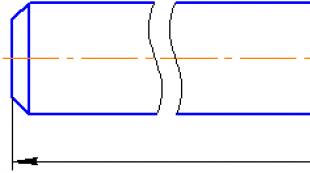
When depicting a product with a break, the dimension line is not interrupted (Figure 3.7). The dimension number, in this case, must correspond to the total length of the part.

Figure 3.7
If it is not possible to place dimensional numbers and arrows between closely spaced solid main or thin lines, they are applied outside (Figure 3.8). The same is done when applying the size of the radius, if the arrow does not fit between the curve and the center of the radius (Figure 3.9).
It is allowed to replace the arrows with dots or serifs applied at an angle of 45 ° to the dimension lines, if it is impossible to place an arrow between the extension lines (Figure 3.10). 
Figure 3.10
Dimensional numbers are not allowed to be divided or crossed by any lines of the drawing. In the place where the dimension number is applied, the axial, center lines or hatching lines are interrupted (Figure 3.11).

Figure 3.11
Dimensional numbers should be applied above the dimension line, as close as possible to its middle (Figure 3.12).

Figure 3.12
Dimensional numbers of linear dimensions with different slopes of dimension lines are arranged as shown in Figure 3.13.
If it is necessary to apply the dimensions of the shaded area, the corresponding dimension number is applied on the shelf of the line - callouts.

Figure 3.13
Angular dimensions are applied as shown in Figure 3.14. 
Figure 3.14
In the area located above the horizontal center line, dimension numbers are placed above the dimension lines from the side of their convexity, in the area located below the horizontal center line - from the side of the concavity of the dimension line.
Dimension numbers above parallel dimension lines should be staggered (Figure 3.15).

Figure 3.15
When specifying the size of the diameter, in all cases, the sign Ø is applied before the size number. Before the dimension number of the diameter (radius) of the sphere, the sign “Ø” (R) is also applied without the inscription “Sphere” (Figure 3.16).

Figure 3.16
If it is difficult to distinguish the sphere from other surfaces in the drawing, it is allowed to put the word "Sphere" or the sign "O", for example, "Sphere Ø18, OR12". The diameter of the sign of the sphere is equal to the height of the dimensional numbers in the drawing.
The dimensions of the square are applied as shown in the drawing (Figure 3.17).

Figure 3.17
The height of the sign must be equal to the height of the dimensional numbers in the drawing.
When drawing a radius dimension, a capital letter is placed in front of the dimension number R. With a larger radius, it is allowed to bring the center closer to the arc, in this case, show the dimension line of the radius with a break at an angle of 90 ° (Figure 3.18). If it is not required to specify the dimensions that determine the position of the center of the circular arc, then the radius dimension line may not be brought to the center and shifted relative to the center (Figure 3.19).
The dimensions of the 45° chamfers are applied as shown in Figure 3.22, A. A chamfer at an angle of 45 ° is allowed, the size of which is 1 mm or less on the scale of the drawing, not to be depicted and its dimensions to be indicated on the shelf of the line - leader, as shown in Figure 3.22, b.
The dimensions of chamfers with other angles are applied according to the general rules - two linear dimensions or linear and angular dimensions (Figure 3.23).
The question of what dimensions should be applied to the drawing is decided taking into account the technology for manufacturing parts and manufacturing control.
As a rule, the dimensions of full circles are set by the diameter, incomplete circles - by the radius.
When it is required to set the distances between circles, for example, representing holes, the distances between the centers of the circles and the distance from the center of any circle to one of the surfaces of the part are specified.
 |
|
| A | b |
Figure 3.22 
Figure 3.23
The surfaces from which the dimensions of other elements of the part are set are called base surfaces or bases.
There are several ways to apply dimensions:
- from the common base (Figure 3.24); the left surface of the plank is selected as the base surface, from which the dimensions of all holes are marked.
Such a system has the advantage, but the dimensions are independent of each other, the error of one of them is not reflected in the others.
- from several bases (Figure 3.25);
- chain (Figure 3.26).

Figure 3.24

Figure 3.25

Figure 3.26
When applying dimensions that determine the distance between evenly spaced identical elements of the product (for example, holes), it is recommended that instead of dimensional chains, apply the size between adjacent elements and the size between the extreme elements in the form of the product of the number of gaps between the elements and the size of the gap (Figure 3.27).
With a large number of dimensions drawn from a common base, it is allowed to apply linear and angular dimensions, as shown in Figure 3.28, while drawing a common dimension line from the “0” mark and dimension numbers are applied in the direction of extension lines at their ends.

Figure 3.27 
Figure 3.28
It is allowed not to apply the dimensions of the radius of conjugation of parallel lines on the drawing (Figure 3.29). 
Figure 3.29
The outer and inner contours of parts during manufacture and control are measured separately, therefore, their dimensions should be applied separately on the drawing (Figure 3.30).

Figure 3.30
Dimensions related to the same structural element (groove, protrusion, hole, etc.) are recommended to be grouped in one place, placing them on the image in which the geometric shape of this element is shown most fully (Figure 3.31).

Figure 3.31
If the part has roundings, the dimensions of the parts of the part are applied without taking into account the roundings, indicating the radii of the roundings (Figure 3.32). 
Figure 3.32
The dimensions of symmetrically located elements of the product (except for holes) are applied once without indicating their number, grouping, as a rule, all dimensions in one place (Figure 3.33).

Figure 3.33
Identical elements located in different parts of the product (for example, holes) are considered as one element if there is no gap between them (Figure 3.34, A) or if these elements are connected by thin solid lines (Figure 3.34, b). In the absence of these conditions, indicate the total number of elements (Figure 3.34, V).
| A | b | V |
Figure 3.34
The dimensions of several identical elements of the product, as a rule, are applied once, with an indication on the shelf of the line - callouts for the number of these elements (Figure 3.35).

Figure 3.35
When applying the dimensions of elements evenly spaced around the circumference (for example, holes), instead of the angular dimensions that determine the relative position of the elements, only their number is indicated (Figure 3.36 - 3.38).
When depicting a part in one projection, the size of its thickness or length is applied, as shown in Figure 3.39. 
Figure 3.39
Dimensions on the drawing are not allowed to be applied in the form closed circuit, except when one of the sizes is specified as reference.
Reference dimensions- dimensions that are not subject to execution according to this drawing and are indicated for greater convenience in using the drawing.
Reference dimensions in the drawing are marked with a “*”, and in the technical requirements they write “* Dimensions for reference”. If all the dimensions in the drawing are reference, they are not marked with a “*” sign, and “Dimensions for reference” are written in the technical requirements.
TO reference dimensions the following sizes apply:
- one of the sizes of a closed dimensional chain (Figure 3.40);
- dimensions transferred from drawings - blanks (Figure 3.41);
- dimensions that determine the position of the elements of the part to be processed on another part (Figure 3.42);

Figure 3.40 
Figure 3.41 
Figure 3.42
- dimensions on the assembly drawing, which determine the limit positions of individual structural elements, for example, piston stroke, valve stem stroke of an internal combustion engine, etc .;
- dimensions on the assembly drawing, parts transferred from the drawing and used as installation and connecting ones;
- overall dimensions on the assembly drawing, transferred from the drawings of parts or being the sum of the dimensions of several parts;
- dimensions of parts (elements) made of sectional, shaped, sheet and other rolled products, if they are fully determined by the designation of the material given in the corresponding column of the main inscription (Figure 3.43).

Figure 3.43
Notes:
- Installation and connecting dimensions are those that determine the dimensions of the elements by which this product is installed at the installation site or attached to another product.
- Dimensions are called dimensions that determine the limiting external (or internal) outlines of the product.
| Ra5 | Ra10 | Ra20 | Ra40 | Ra5 | Ra10 | Ra20 | Ra40 | Ra5 | Ra10 | Ra20 | Ra40 |
|---|---|---|---|---|---|---|---|---|---|---|---|
| 0,100 | 0,100 | 0,100 | 0,100 | 1,0 | 1,0 | 1,0 | 1,0 | 10 | 10 | 10 | 10 |
| 0,105 | 1,05 | 10,5 | |||||||||
| 0,110 | 0,110 | 1,1 | 1,1 | 11 | 11 | ||||||
| 0,115 | 1,15 | 11,5 | |||||||||
| 0,120 | 0,120 | 0,120 | 1,2 | 1,2 | 1,2 | 12 | 12 | 12 | |||
| 0,130 | 1,3 | 13 | |||||||||
| 0,140 | 0,140 | 1,4 | 1,4 | 14 | 14 | ||||||
| 0,150 | 1,5 | 15 | |||||||||
| 0,160 | 0,160 | 0,160 | 0,160 | 1,6 | 1,6 | 1,6 | 1,6 | 16 | 16 | 16 | 16 |
| 0,170 | 1,7 | 17 | |||||||||
| 0,180 | 0,180 | 1,8 | 1,8 | 18 | 18 | ||||||
| 0,190 | 1,9 | 19 | |||||||||
| 0,200 | 0,200 | 0,200 | 2,0 | 2,0 | 2,0 | 20 | 20 | 20 | |||
| 0,210 | 2,1 | 21 | |||||||||
| 0,220 | 0,220 | 2,2 | 2,2 | 22 | 22 | ||||||
| 0,240 | 2,4 | 24 | |||||||||
| 0,250 | 0,250 | 0,250 | 0,250 | 2,5 | 2,5 | 2,5 | 2,5 | 25 | 25 | 25 | 25 |
| 0,260 | 2,6 | 26 | |||||||||
| 0,280 | 0,280 | 2,8 | 2,8 | 28 | 28 | ||||||
| 0,300 | 3,0 | 30 | |||||||||
| 0,320 | 0,320 | 0,320 | 3,2 | 3,2 | 3,2 | 32 | 32 | 32 | |||
| 0,340 | 3,4 | 34 | |||||||||
| 0,360 | 0,360 | 3,6 | 3,6 | 36 | 36 | ||||||
| 0,380 | 3,8 | 38 | |||||||||
| 0,400 | 0,400 | 0,400 | 0,400 | 4,0 | 4,0 | 4,0 | 4,0 | 40 | 40 | 40 | 40 |
| 0,420 | 4,2 | 42 | |||||||||
| 0,450 | 0,450 | 4,5 | 4,5 | 45 | 45 | ||||||
| 0,480 | 4,8 | 48 | |||||||||
| 0,500 | 0,500 | 0,500 | 5,0 | 5,0 | 5,0 | 50 | 50 | 50 | |||
| 0,530 | 5,3 | 53 | |||||||||
| 0,560 | 0,560 | 5,6 | 5,6 | 56 | 56 | ||||||
| 0,600 | 6,0 | 60 | |||||||||
| 0,630 | 0,630 | 0,630 | 0,630 | 6,3 | 6,3 | 6,3 | 6,3 | 63 | 63 | 63 | 63 |
| 0,670 | 6,7 | 67 | |||||||||
| 0,710 | 0,710 | 7,1 | 7,1 | 71 | 71 | ||||||
| 0,750 | 7,8 | 75 | |||||||||
| 0,800 | 0,800 | 0,800 | 8,0 | 8,0 | 8,0 | 80 | 80 | 80 | |||
| 0,850 | 8,5 | 85 | |||||||||
| 0,900 | 0,900 | 9,0 | 9,0 | 90 | 90 | ||||||
| 0,950 | 9,5 | 95 | |||||||||
| 100 | 100 | 100 | 100 | 160 | 160 | 160 | 160 | 250 | 250 | 250 | 250 |
| 105 | 170 | 260 | |||||||||
| 110 | 110 | 180 | 280 | 280 | |||||||
| 120 | 190 | 300 | |||||||||
| 125 | 125 | 125 | 200 | 200 | 200 | 320 | 320 | 320 | |||
| 130 | 210 | 340 | |||||||||
| 140 | 140 | 220 | 220 | 360 | 360 | ||||||
| 150 | 240 | 380 |
GOST 2.301-68 "ESKD. Formats»
1. This standard establishes the formats of sheets of drawings and other documents made in electronic and (or) paper form, provided for by the standards for design documentation of all industries and construction.
2. Sheet formats are determined by the dimensions of the outer frame (made with a thin line) of originals, originals, duplicates, copies (Fig. 1).
When outputting a document in electronic form on paper with the dimensions of the sides of the sheet, coinciding with those indicated in Table. 1, the outer frame of the format may be omitted. If the dimensions of the sides of the sheet are larger than those indicated in Table. 1 , then the outer frame of the format should be played.
3. Format with side dimensions 1189x841 mm, the area of which is 1 m 2 , and other formats obtained by successively dividing it into two equal parts parallel to the smaller side of the corresponding format, are taken as the main ones.
4. The designations and dimensions of the sides of the main formats must correspond to those indicated in tab. 1 .
Table 1
Format designation |
Dimensions of the sides of the format, mm |
If necessary, it is allowed to use the A5 format with side dimensions of 148x210 mm.
5. It is allowed to use additional formats formed by increasing the short sides of the main formats by a multiple of their sizes.
The sizes of derived formats, as a rule, should be selected according to the table. 2. The designation of the derived format is made up of the designation of the main format and its multiplicity according to Table. 2 , for example,
A0x2, A4x8, etc.
table 2 |
|||||||||||
multiplicity |
|||||||||||
6. Limit deviations of the sides of the formats - according to the table. 3 . |
|||||||||||
Table 3 |
|||||||||||
Sizes of the sides of the formats |
Limit deviations |
||||||||||
St. 150 to 600 |
|||||||||||
4-6.
7.8. (Deleted, Rev. No. 1).
9. Documents in electronic form in their requisite part must contain the designation of the paper sheet format, upon output to which the display scale will correspond to the specified one.
(Introduced additionally, Rev. No. 3).
GOST 2.302-68 "ESKD. Scales»
1. This standard establishes the scale of images and their designation on the drawings of all industries and construction. The standard does not apply to photographic drawings, as well as illustrations in printed publications, etc.
(Revised edition, No. 2).
2a. For the purposes of this International Standard, the following terms apply with their respective definitions:
scale: The ratio of the linear dimension of a segment in the drawing to the corresponding linear dimension of the same segment in kind;
life size scale: Scale with ratio
magnification scale: A scale with a ratio greater than
1:1 (2:1, etc.);
reduction scale: A scale with a ratio less than
1:1 (1:2, etc.).
(Introduced additionally, Amendment No. 2).
2. The scale of images in the drawings must be selected from the following series:
3. When designing master plans for large objects, it is allowed to use scales
1:2000; 1:5000; 1:10000; 1:20000; 1:25000; 1:50000.
4. In necessary cases, it is allowed to use magnification scales (100n):1, where n is an integer.
5. The scale indicated in the column of the main inscription of the drawing intended for this should be indicated by type 1: 1; 1:2; 2:1 etc.
Documents in electronic form in their requisite part must contain a requisite indicating the accepted scale of the image. When outputting documents in electronic form to paper, the scale of the image must correspond to the specified one.
(Revised edition, Rev. No. 3).

GOST 2.303-68 "ESKD. Lines»
1. This standard establishes the styles and main purposes of lines in the drawings of all industries and construction, performed in paper and (or) electronic form.
Special purpose of lines (image of threads, slots, boundaries of zones with different roughness, etc.) are defined in the relevant standards of the Unified Design Documentation System.
(Changed edition, Rev. No. 1, 2, 3).
2. The name, style, thickness of the lines in relation to the thickness of the main line and the main purpose of the lines must correspond to those indicated in Table. 1 . Examples of the use of lines are shown in Fig. 1-9.
(Revised edition, Rev. No. 1).
3. For cuts and sections, it is allowed to connect the ends of an open line with a dash-dotted thin line.
(Revised edition, Rev. No. 3).
4. In construction drawings in sections, visible contour lines that do not fall into the section plane are allowed to be drawn with a solid thin line(dev. 9).
5. The thickness of the solid main line s should be in the range from 0.5 to 1.4 mm, depending on the size and complexity of the image, as well as on the format of the drawing.
The thickness of lines of the same type must be the same for all images in this drawing, drawn at the same scale.
(Revised edition, Rev. No. 1).
Table 1 |
||||
Line thickness by |
||||
Name |
inscription |
towards |
Main purpose |
|
core thickness |
||||
Lines of visible contour |
||||
Transition lines visible |
||||
1. Solid thick |
Section Contour Lines |
|||
(taken out and included in |
||||
section composition) |
||||
Contour lines superimposed |
||||
Dimension and extension lines |
||||
Hatching lines |
||||
Leader lines |
||||
Lead line shelves and |
||||
underline inscriptions |
||||
2. Solid thin |
s/3 to s/2 |
Lines for the image |
||
border details |
||||
(?situation?) |
||||
Callout limit lines |
||||
elements on views, sections |
||||
and sections |
||||
transition lines |
||||
imaginary |
||||
Plane traces, lines |
||||
constructing characteristic |
||||
points at special |
|||
constructions |
|||
3. Solid |
Cliff lines |
||
s/3 to s/2 |
Lines of demarcation of the view and |
||
wavy |
|||
4. Dashed |
s/3 to s/2 |
Hidden contour lines |
|
Transition lines invisible |
|||
Lines axial and center |
|||
5. Dash-dotted |
Section lines, which are |
||
s/3 to s/2 |
axes of symmetry for |
||
imposed or delivered |
|||
Lines denoting |
|||
surfaces to be |
|||
heat treatment or |
|||
6. Dash-dotted |
s/3 to 2/3s |
coverage |
|
thickened |
Lines for the image |
||
elements located |
|||
in front of the cutting plane |
|||
(?overlay projection?) |
|||
7. Open |
s to 1.5s |
Section lines |
|
8. Solid thin s |
s/3 to s/2 |
Long break lines |
|
kinks |
|||
Fold lines on reamers. |
|||
Lines for the image |
|||
9. Dash-dotted with |
parts of products in extreme or |
||
two points |
s/3 to s/2 |
intermediate provisions |
|
Lines for the image |
|||
sweep combined with |
|||

 Drawing 1
  Drawing 2
  Drawing 3
 Drawing 4
  Drawing 5
  Drawing 6
 Drawing 7
  Drawing 8
  Drawing 9
Note. Position numbers on hell. 1-9 correspond to the numbers of items in Table. 1 .
6. The smallest thickness of the lines and the smallest distance between the lines, depending on the format of the drawing, must correspond to those indicated in Table. 2.
table 2 |
||||||
The smallest line thickness in mm, |
The smallest distance between lines |
|||||
Drawing Format |
completed |
in mm, made |
||||
in pencil |
in pencil |
|||||
larger side 841 |
||||||
mm or more |
||||||
larger side |
||||||
less than 841 mm |
||||||
7. The length of strokes in dashed and dash-dotted lines should be chosen depending on the size of the image.
8. The strokes in the line should be approximately the same length.
9. The spaces between dashes in a line should be approximately the same length.
10. Dash-dotted lines should intersect and end with dashes.
11. Dash-dotted lines used as center lines should be replaced by solid thin lines if the diameter of the circle or the dimensions of other geometric shapes in the image is less than 12 mm(dev. 10).

 Drawing 10
GOST 2.304-81 "ESKD. Fonts»
1. Terms and Definitions
1.1. The font size h is a value determined by the height of the capital letters in millimeters.
1.2. Capital letters height h is measured perpendicular to the base of the string.
The height of lowercase letters c is determined from the ratio of their height (without processes h) to the font size h, for example, c \u003d 7/10 h (Fig. 1 and 2).
1.3. The width of the letter g is the largest width of the letter, measured in accordance with the drawing. 1 and 2 , is defined in relation to the font size h , for example, g = 6/10 h , or in relation to the font line thickness d , for example, g = 6 d .
1.4. Font Line Thickness d - thickness, determined depending on the type and height of the font.
1.5. Auxiliary grid- a grid formed by auxiliary lines into which letters fit. The pitch of the auxiliary grid lines is determined depending on the thickness of the font lines d (Fig. 3).
 Drawing 3
2. Font types and sizes
2.1. The following font types are installed:
type A without slope (d = 1/14 h ) with parameters given in
tab. 1 ;
type A with an inclination of about 75° (d = 1/14 h) with the parameters given in table. 1 ;
type B without slope (d = 1/10 h ) with the parameters given in
tab. 2;
type B with an inclination of about 75° (d = 1/10 h) with the parameters given in Table. 2.
Table 1 Type A font (d = h/14)
Font Options |
Designation |
Relative |
Dimensions, mm |
|||||||||||||||
Font size - |
||||||||||||||||||
capital height |
||||||||||||||||||
lowercase height |
||||||||||||||||||
Distance between |
||||||||||||||||||
Minimum step |
||||||||||||||||||
rows (height |
||||||||||||||||||
auxiliary |
||||||||||||||||||
Minimum |
||||||||||||||||||
distance between |
||||||||||||||||||
Line thickness |
||||||||||||||||||
Table 2 Type B font (d = h/10) |
||||||||||||||||||
Options |
Notation |
Relatives |
Dimensions, mm |
|||||||||||||||
Font size |
||||||||||||||||||
capital letters |
||||||||||||||||||
lowercase height |
||||||||||||||||||
Distance |
||||||||||||||||||
between letters |
||||||||||||||||||
Minimum |
||||||||||||||||||
line pitch |
||||||||||||||||||
auxiliary |
||||||||||||||||||
Minimum |
||||||||||||||||||
distance |
||||||||||||||||||
between words |
||||||||||||||||||
Line thickness |
||||||||||||||||||
| e , separated by a punctuation mark, is the distance between the punctuation mark and the word following it. | ||||||||||||||||||
 Drawing 4
 Drawing 7
 Drawing 8
 Drawing 12
Contacts .
1.1 Formats
Drawings are performed on sheets of a certain format (size).
Sheet formats are determined by the dimensions of the outer frame of the drawing, made with a thin line.
According to GOST 2.301-68 *, the dimensions of the main formats are obtained by successively dividing the A0 format, with side dimensions of 841x1189 mm, the area of \u200b\u200bwhich is 1 m 2, into two equal parts parallel to the smaller side (Figure 1.1). The number in the designation shows how many times this action was performed.
The designations and sizes of the main formats must correspond to those indicated in Table 1.
Table 1 - Basic formats
| Format designation | A0 | A1 | A2 | A3 | A4 |
|---|---|---|---|---|---|
| Dimensions of the sides of the format, mm | 841х1189 | 594x841 | 420 x594 | 297 x420 | 210 x297 |
It is allowed to use additional formats formed by increasing the sides of the main formats by a multiple of their sizes. In this case, the magnification factor must be an integer.
The sizes of the derived formats, as a rule, should be selected from Table 2. The designation of the derived format is made up of the designation of the main format and its multiplicity according to the data in Table 2: for example, A0x2, A4x8, etc.
Table 2 - Additional formats
| multiplicity | A0 | A1 | A2 | A3 | A4 |
|---|---|---|---|---|---|
| 2 | 1189*1682 | — | — | — | — |
| 3 | 1189*2523 | 841*1783 | 594*1261 | 420*891 | 297*630 |
| 4 | — | 841*2378 | 594*1682 | 420*1189 | 297*841 |
| 5 | — | — | 594*2102 | 420*1486 | 297*1051 |
| 6 | — | — | — | 420*1783 | 297*1261 |
| 7 | — | — | — | 420*2080 | 297*1471 |
| 8 | — | — | — | — | 297*1682 |
| 9 | — | — | — | — | 297*1892 |
1.2 Scale
scale called the ratio of the linear dimensions of the image of an object in the drawing to the actual dimensions of this object.
The scale indicated in the column of the main inscription of the drawing intended for this should be indicated by type 1:1, 2:1, etc., and in other cases - by type (1:1), (1:2), (2:1), etc. (Table 3).
According to GOST 2.302 - 68 * scales of images in the drawings must be selected from the following row - Table 3.
Table 3 - Scales
1.3 Lines
For the image of objects in the drawings, GOST 2.303 - 68 * establishes the style, thickness and main purposes of the lines in the drawing (Table 4).
Thickness of the solid main line S should be within 0,5 before 1.4 mm depending on the size and complexity of the image, as well as on the format of the drawing. The thickness of lines of the same type must be the same for all images in this drawing, drawn at the same scale.
The stroke length of the dashed lines should be approximately 10 times the stroke thickness, and the length of the strokes of the dash-dotted line is selected depending on the size of the image. The strokes in the line should be approximately the same length. The gaps between them should also be approximately the same. Dash-dotted lines should intersect and end with dashes. Dash-dotted lines used as center lines should be replaced by solid thin lines if the diameter of the circle or the dimensions of other geometric shapes in the image is less than 12 mm.
Table 4 - Lines
| Name | inscription | Line thickness in relation to the main line thickness | Main purpose |
|---|---|---|---|
| S | The lines of the visible contour transition lines are visible, the contour lines of the section. | ||
| From S/3 before S/2 | Superimposed section contour lines, dimension and extension lines, hatch lines, leader lines, leader line shelves | ||
| From S/3 before S/2 | Break lines, view and section demarcation lines | ||
 |
From S/3 before S/2 | Invisible contour lines, transition lines invisible | |
 |
From S/3 before S/2 | Axial and center lines, section lines, which are the axes of symmetry for superimposed or extended sections. | |
 |
From S/2 before 2/3*S | Lines indicating surfaces to be heat treated or coated | |
 |
From S before 1.5*S | Section lines | |
| From S/3 before S/2 | Long break lines | ||

|
From S/3 before S/2 | Fold lines on scans, lines for depicting parts of products in extreme or intermediate positions, lines for depicting a scan combined with a view. |
1.4 Title block
The drawing is drawn with a frame, which is drawn with a solid main line at a distance of 5 mm from the right, lower and upper sides of the outer frame of the drawing. On the left side, a 20 mm wide field is left, which serves for filing and stitching drawings (Figure 1.2).

The main inscription is placed in the lower right corner of the design documents. On sheets of A4 format, the main inscription is placed along the short side of the leaf, on sheets of A3 format and more, it is allowed to place the main inscription both along the long and along the short side of the sheet. The main inscriptions, additional columns to them are made with solid main and solid thin lines in accordance with GOST 2.303 - 68 * (Figure 1.3).
The main inscription in form 1 is used in the drawings of instrumentation and mechanical engineering.
The main inscription in form 2 is used in the specification and other text documents - the first sheet, in form 3 - subsequent sheets. 
form 1 
form 2 
form 2a
In the columns of the main inscription indicate:
- in column 1 - the name of the product;
- in column 2 - the designation of the document;
- in column 3 - designation of the material of the part;
- in column 4 - the letter assigned to this document;
- in column 5 - the mass of the product;
- in column 6 - scale;
- in column 7 - the serial number of the sheet (on documents consisting of one sheet, the column is not filled out);
- in column 8 - the total number of sheets of the document (the column is filled out only on the first sheet);
- in column 9 - the name of the enterprise issuing the document;
- in column 10 - the functions of the performers are indicated: “Developed”, “Checked”;
- in column 11 - the names of the persons who signed the document;
- in column 12 - signatures of persons whose names are indicated in column 11;
- in column 13 - date;
- columns 14-18 are filled in on the production drawings.
1.5. Fonts
GOST 2.304-81 * defines the style, dimensions and rules for making inscriptions on drawings and other design documents.
The inclination of letters and numbers to the base of the line should be about 75°.
Font size ( h)- a value equal to the height of capital letters in mm.
Capital letters height h measured perpendicular to the base of the string. The height of lowercase letters c is determined from the ratio of their height (without processes k) to font size h, For example, c=7/10*h.
Letter width ( q)- the largest letter width is determined in relation to the font size h, For example, q=6/10h, or in relation to the line thickness of the font d, For example, q=6d.
Font line thickness ( d)- thickness, determined depending on the type and height of the font.
Auxiliary grid - a grid formed by auxiliary lines into which letters fit. The step of the auxiliary grid lines is determined depending on the thickness of the font lines d(Figure 1.4).
When drawing up drawings and other design documents, it is recommended to use type B font with an inclination of 75° ( d=1/10h) with the parameters given in Table 5.
Table 5 - Fonts
| Font Options | Designation | Relative size | Dimensions | ||||||||
|---|---|---|---|---|---|---|---|---|---|---|---|
| Font size - capital letters height | h | (10/10)h | 10d | 1,8 | 2,5 | 3,5 | 5,0 | 7,0 | 10,0 | 14,0 | 20,0 |
| Lower case height | c | (7/10)h | 7d | 1,3 | 1,8 | 2,5 | 3,5 | 5,0 | 7,0 | 10,0 | 14,0 |
| Letter spacing | a | (2/10)h | 2d | 0,35 | 0,5 | 0,7 | 1,0 | 1,4 | 2,0 | 2,8 | 4,0 |
| Minimum row spacing (height, auxiliary grid) | b | (17/10)h | 17d | 3,1 | 4,3 | 6,0 | 8,5 | 12,0 | 17,0 | 24,0 | 34,0 |
| Minimum spacing between words | e | (6/10)h | 6d | 1,1 | 1,5 | 2,1 | 3,0 | 4,2 | 6,0 | 8,4 | 12,0 |
| Font Line Thickness | d | (1/10)h | d | 0,18 | 0,25 | 0,35 | 0,5 | 0,7 | 1,0 | 1,4 | 2,0 |
The following font sizes are set: (1.8); 2.5; 3.5; 5; 7; 10; 14; 20; 28; 40. 
For tutoring in engineering graphics (drawing), you can contact in any way convenient for you in the section Contacts . Full-time and distance learning via Skype is possible: 1000 rubles/ac.h.
1. Rules for the design of drawings1.1. The concept of ESKD standards. If every engineer or draftsman performed and designed the drawings in his own way, without observing uniform rules, then such drawings would not be understandable to others. To avoid this, the state standards of the Unified System for Design Documentation (ESKD) have been adopted and are in force in the USSR.
ESKD standards are regulatory documents that establish uniform rules for the implementation and execution of design documents in all industries. Design documents include drawings of parts, assembly drawings, diagrams, some text documents, etc.
Standards are set not only for design documents, but also for certain types of products manufactured by our enterprises. State standards (GOST) are mandatory for all enterprises and individuals.
Each standard is assigned its own number with the simultaneous indication of the year of its registration.
The standards are revised from time to time. Changes in standards are associated with the development of industry and the improvement of engineering graphics.
For the first time in our country, standards for drawings were introduced in 1928 under the name "Drawings for all types of mechanical engineering." Later they were replaced by new ones.
1.2. Formats. The main text of the drawing. Drawings and other design documents for industry and construction are performed on sheets of certain sizes.
For economical use of paper, ease of storing drawings and using them, the standard establishes certain sheet formats that are outlined with a thin line. At school, you will use a format whose sides are 297X210 mm. It is designated A4.
Each drawing must have a frame that limits its field (Fig. 18). The frame lines are solid thick main lines. They are carried out from above, to the right and from below at a distance of 5 mm from the outer frame, performed by a solid thin line along which the sheets are cut. On the left side - at a distance of 20 mm from it. This strip is left for filing drawings.
Rice. 18. Making an A4 sheet
In the drawings, the main inscription is placed in the lower right corner (see Fig. 18). Its form, dimensions and content are established by the standard. On educational school drawings, you will perform the main inscription in the form of a rectangle with sides of 22X145 mm (Fig. 19, a). A sample of the completed title block is shown in Figure 19, b.

Rice. 19. The main inscription of the training drawing
Production drawings, performed on A4 sheets, are placed only vertically, and the main inscription on them is only along the short side. In drawings of other formats, the title block can be placed along both the long and short sides.
As an exception, on A4 training drawings, the main inscription is allowed to be placed both along the long and along the short side of the sheet.
Before starting the drawing, the sheet is applied to the drawing board. To do this, attach it with one button, for example, in the upper left corner. Then a T-square is placed on the board and the upper edge of the sheet is placed parallel to its edge, as shown in Figure 20. Pressing a sheet of paper to the board, attach it with buttons, first in the lower right corner, and then in the other corners.

Rice. 20. Preparing the sheet for work
The frame and columns of the main inscription are made with a solid thick line.
- What are the dimensions of an A4 sheet? At what distance from the outer frame should the drawing frame lines be drawn? Where is the title block placed on the drawing? Name its dimensions. Consider Figure 19 and list what information is indicated in it.
1.3. Lines. When making drawings, lines of various thicknesses and styles are used. Each of them has its own purpose.

Rice. 21. Drawing lines
Figure 21 shows an image of a part called a roller. As you can see, the detail drawing contains different lines. In order for the image to be clear to everyone, the state standard establishes the style of lines and indicates their main purpose for all drawings of industry and construction. In the lessons of technical and service labor, you have already used various lines. Let's remember them.

In conclusion, it should be noted that the thickness of lines of the same type should be the same for all images in a given drawing.
Information about the lines of the drawing is given on the first flyleaf.
- What is the purpose of a solid thick main line?
- What is a dashed line? Where is it used? What is the thickness of this line?
- Where is a dash-dot thin line used in a drawing? What is its thickness?
- In what cases is a solid thin line used in a drawing? How thick should it be?
- Which line shows the fold line on the scan?
In Figure 23 you see a picture of the part. Various lines are marked on it with the numbers 1,2, etc. Make a table in your workbook according to this sample and fill it out.


Rice. 23. Task for exercises
EXAMPLE #1
Prepare an A4 sheet of drawing paper. Draw the frame and columns of the title block according to the dimensions indicated in Figure 19. Draw different lines, as shown in Figure 24. You can also choose a different arrangement of line groups on the sheet.

Rice. 24. example number 1
The main inscription can be placed both along the short and along the long side of the sheet.
1.4. Drawing fonts. Sizes of letters and numbers of the drawing font. All inscriptions on the drawings must be made in drawing font (Fig. 25). The style of letters and numbers of the drawing font is established by the standard. The standard defines the height and width of letters and numbers, the thickness of stroke lines, the spacing between letters, words, and lines.

Rice. 25. Inscriptions on drawings
An example of building one of the letters in the auxiliary grid is shown in Figure 26.
Rice. 26. An example of building a letter
The font can be both slanted (about 75°) and non-slanted.
The standard specifies the following font sizes: 1.8 (not recommended, but allowed); 2.5; 3.5; 5; 7; 10; 14; 20; 28; 40. The size (h) of the font is taken as the value determined by the height of uppercase (capital) letters in millimeters. The height of the letter is measured perpendicular to the base of the line. The lower elements of the letters D, C, U and the upper element of the letter Y are performed due to the spaces between the lines.
The thickness (d) of the font line is determined depending on the height of the font. It is equal to 0.1h;. The width (g) of the letter is chosen to be 0.6h or 6d. The width of the letters A, D, Zh, M, F, X, C, SH, W, b, Y, Yu is 1 or 2d more than this value (including the lower and upper elements), and the width of the letters Г, 3, С is less than d.
The height of the lowercase letters roughly matches the height of the next smaller font size. Thus, the height of lowercase letters of size 10 is 7, of size 7 is 5, and so on. The width of most lowercase letters is 5d. The width of the letters a, m, c, b is 6d, the width of the letters w, t, f, w, u, s, u is 7d, and the letters h, c are 4d.
The distance between letters and numbers in words is taken equal to 0.2h or 2d, between words and numbers -0.6h or 6d. The distance between the lower lines of the lines is taken equal to 1.7h or 17d.
The standard also establishes another type of font - type A, narrower than just considered.
The height of letters and numbers in pencil drawings must be at least 3.5 mm.
The outline of the Latin alphabet according to GOST is shown in Figure 27.

Rice. 27. Latin script
How to write in cursive font. It is necessary to draw up drawings with inscriptions carefully. Indistinctly made inscriptions or carelessly applied figures of different numbers can be misunderstood when reading the drawing.
To learn how to write beautifully in a drawing font, first a grid is drawn for each letter (Fig. 28). After mastering the skills of writing letters and numbers, you can only draw the top and bottom lines of the line.

Rice. 28. Examples of inscriptions in drawing font
The contours of the letters are outlined with thin lines. After making sure that the letters are written correctly, circle them with a soft pencil.
For the letters G, D, I, I, L, M, P, T, X, C, W, W, only two auxiliary lines can be drawn at a distance equal to their height A.
For letters B, C, E, N. R, U, H, b, Y, b. Between two horizontal lines, one more should be added in the middle, but with which their middle elements perform. And for the letters 3, O, F, Yu, four lines are drawn, where the middle lines indicate the boundaries of the fillets.
To quickly make inscriptions in a drawing font, various stencils are sometimes used. You will fill in the main inscription in font 3.5, the name of the drawing in font 7 or 5.
- What is the font size?
- What is the width of the capital letters?
- What is the height of lowercase letters of size 14? What is their width?
- Complete a few inscriptions in the workbook for the teacher's assignment. You can, for example, write your last name, first name, home address.
- Fill in the main inscription on the sheet of graphic work No. 1 with the following text: drew (surname), checked (name of the teacher), school, class, drawing No. 1, the name of the work "Lines".
1.5. How to measure. To determine the size of the depicted product or any part of it, dimensions are applied to the drawing. Dimensions are divided into linear and angular. Linear dimensions characterize the length, width, thickness, height, diameter or radius of the measured part of the product. The angular dimension characterizes the magnitude of the angle.
The linear dimensions in the drawings are indicated in millimeters, but the designation of the unit of measure is not applied. Angular dimensions are indicated in degrees, minutes and seconds with the designation of the unit of measurement.
The total number of dimensions in the drawing should be the smallest, but sufficient for the manufacture and control of the product.
The rules for sizing are set by the standard. Some of them you already know. Let's remind them.
1. Dimensions in the drawings are indicated by dimensional numbers and dimension lines. To do this, first draw extension lines perpendicular to the segment, the size of which is indicated (Fig. 29, a). Then, at a distance of at least 10 mm from the contour of the part, a dimension line parallel to it is drawn. The dimension line is limited on both sides by arrows. What should be the arrow is shown in Figure 29, b. The extension lines extend beyond the ends of the arrows of the dimension line by 1...5 mm. Extension and dimension lines are drawn with a solid thin line. Above the dimension line, closer to its middle, a dimension number is applied.

Rice. 29. Drawing linear dimensions
2. If there are several dimension lines parallel to each other in the drawing, then a smaller size is applied closer to the image. So, in Figure 29, first the size 5 is applied, and then 26, so that the extension and dimension lines in the drawing do not intersect. The distance between parallel dimension lines must be at least 7 mm.
3. To indicate the diameter, a special sign is applied in front of the dimension number - a circle crossed out with a line (Fig. 30). If the dimension number does not fit inside the circle, it is taken out of the circle, as shown in Figure 30, c and d. The same is done when applying the size of a straight segment (see Fig. 29, c).

Rice. 30. Applying the size of circles
4. To designate the radius, a capital Latin letter R is written in front of the dimension number (Fig. 31, a). The dimension line to indicate the radius is drawn, as a rule, from the center of the arc and ends with an arrow on one side, resting on the point of the circular arc.

Rice. 31. Dimensioning Arcs and Angle
5. When specifying the size of the corner, the dimension line is drawn in the form of an arc of a circle with the center at the apex of the corner (Fig. 31, b).
6. Before the dimension number indicating the side of the square element, a "square" sign is applied (Fig. 32). In this case, the height of the sign is equal to the height of the digits.

Rice. 32. Drawing the size of the square
7. If the dimension line is located vertically or obliquely, then the dimension numbers are arranged as shown in Figures 29, c; thirty; 31.
8. If the part has several identical elements, then it is recommended to put the size of only one of them on the drawing, indicating the quantity. For example, the entry in the drawing “3 holes. 0 10" means that the part has three identical holes with a diameter of 10 mm.
9. When depicting flat parts in one projection, the thickness of the part is indicated, as shown in Figure 29, c. Please note that in front of the dimension number indicating the thickness of the part, there is a small Latin letter 5.
10. It is allowed to indicate the length of the part in a similar way (Fig. 33), but in this case they write a Latin letter before the size number l.

Rice. 33. Drawing the size of the length of the part
- In what units are linear dimensions expressed on engineering drawings?
- How thick should extension and dimension lines be?
- What distance is left between the image outline and the dimension lines? between dimension lines?
- How are dimensional numbers applied on inclined dimension lines?
- What signs and letters are applied before the size number when indicating the size of diameters and radii?

Rice. 34. Task for exercises
- Redraw in a workbook, maintaining proportions, the image of the part given in Figure 34, increasing it by 2 times. Apply the required dimensions, indicate the thickness of the part (it is 4 mm).
- Draw circles in the workbook with diameters of 40, 30, 20 and 10 mm. Enter their dimensions. Draw circular arcs with radii of 40, 30, 20 and 10 mm and dimension.
1.6. Scales. In practice, you have to make images of very large parts, for example, parts of an aircraft, a ship, a car, and very small ones - parts of a clockwork, some instruments, etc. Images of large parts may not fit on sheets of a standard format. Small details that are barely visible to the naked eye cannot be drawn in full size with the available drawing tools. Therefore, when drawing large parts, their image is reduced, and small ones are increased compared to the actual dimensions.
Scale is the ratio of the linear dimensions of the image of an object to the actual. The scale of the images and their designation in the drawings sets the standard.
Reduction scale-1:2; 1:2.5; 1:4; 1:5; 1:10 etc.
Natural size-1:1.
Magnification scale-2:1; 2.5:1; 4:1; 5:1; 10:1 etc.
The most desirable scale is 1:1. In this case, you do not need to recalculate the dimensions when rendering the image.
Scales are written as follows: M1:1; M1:2; M5:1, etc. If the scale is indicated on the drawing in the main inscription specially designed for this, then the letter M is not written before the scale designation.
It should be remembered that, no matter what scale the image is made, the dimensions in the drawing are applied to the actual ones, that is, those that the part should have in kind (Fig. 35).
The angular dimensions do not change when the image is reduced or enlarged.
- What is the scale for?
- What is called scale?
- What scales of increase are known to you, established by the standard? What scale of reduction do you know?
- What do the entries mean: М1:5; M1:1; M10:1?

Rice. 35. Drawing gasket, made in different scales
EXAMPLE #2
Drawing "flat part"
Make drawings of the “Gasket” parts according to the existing halves of the images separated by the axis of symmetry (Fig. 36). Apply dimensions, indicate the thickness of the part (5 mm).
Do the work on an A4 sheet. Image scale 2:1.
Instructions for work. Figure 36 shows only half of the part image. You need to imagine how the part will look like in full, keeping in mind the symmetry, sketch its image on a separate sheet. Then you should proceed to the execution of the drawing.
A frame is drawn on an A4 sheet and space is allocated for the main inscription (22X145 mm). The center of the working field of the drawing is determined and the image is built from it.
First, axes of symmetry are drawn, a rectangle is built with thin lines, corresponding to the general shape of the part. After that, images of rectangular elements of the part are marked.

Rice. 36. example number 2
Having determined the position of the centers of the circle and the semicircle, they are carried out. Apply the dimensions of the elements and overall, i.e., the largest in length and height, the dimensions of the part, indicate its thickness.
Outline the drawing with lines established by the standard: first - circles, then - horizontal and vertical lines. Fill in the main inscription and check the drawing.