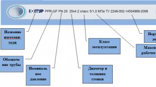
Do-it-yourself installation of an electric storage water heater: connection diagrams
Nothing will prevent you from installing a storage-type electric water heater with your own hands if you are “friends” with tools. Let's look at the main connection diagrams that will help you understand the installation details and connect the boiler to the water supply and the mains.
An electric storage water heater is a heat-insulated storage tank with heating elements (heaters) inside, fittings for supplying cold and discharging hot water and automatic temperature control. They can be wall and floor arrangement, horizontal and vertical. Each type of installation has its own characteristics.
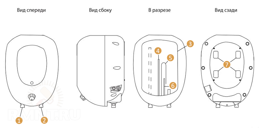 The device of a wall-mounted storage water heater Haier: 1 - hot water outlet; 2 - cold water supply; 3 - storage tank; 4 - thermocouple; 5 - heating element; 6 - magnesium anode (corrosion protection); 7 - brackets
Features of installing a wall-mounted water heater
First of all, when installing a wall-mounted water heater, you need to make sure that the wall can withstand the additional load. Equipment manufacturers recommend taking four times the weight of the boiler filled with water when calculating. But since few people can correctly calculate the loads of building structures, the following rules should be followed:
- The load-bearing wall is able to withstand the weight of almost any domestic water heater.
- When installing a boiler on piers, especially in Khrushchevs, or walls made of hollow bricks, small-capacity tanks can still be hung simply on anchors. More or less capacious drives are best installed on a wall reinforced with racks or mounted on through bolts fixed with a coupler for reliability.
 Mounting the storage boiler to the wall
Schemes of connection to water of a wall-mounted storage water heater
The fittings for supplying cold and discharging hot water are located at the bottom of the wall-mounted boiler, and are marked in blue and red, respectively. The connection to the trunk can be made in two ways:
- no security group;
- with the security team.
Schemes without a safety group can be used when connecting a water heater designed for pressure exceeding the pressure in the main cold water supply, if this pressure is stable. In case of unstable, strong pressure in the line, preference should be given to connecting through a security group.
In any case, the connection and installation of the water supply system begins with the insertion of tees into the pipelines of cold and hot water after the taps installed at the entrance of the water supply to the apartment.

Attention! If the pipes in the house have not changed for a long time, you need to check their condition before work. It may be necessary to replace rusted steel pipes with new ones.
Branches are made from the tees to connect the water heater. When the boiler is in operation, the hot water tap must be completely closed. Cold water freely flows to heating, to mixers, to the toilet bowl.
On the boiler, a check safety valve is screwed onto the cold water inlet. It serves as protection against thermal expansion of water in the storage tank, periodically bleeding off its excess. From the drain hole of the valve, a drainage tube is mounted, which should be directed downward and fall into the tank or sewer freely, without kinks that could prevent the draining of excess water in the tank.
 Check relief valve
Shut-off valves cannot be installed between the valve and the water heater. But the tee, on the branch of which a tap is installed to empty the tank, can be installed, and is even recommended by manufacturers. The pipe or hose from it must be brought to the sewer, or connected with a tee to the cold water supply pipe to the safety valve.
At the outlet of the hot water boiler and at the inlet of cold water, immediately after the check valve, it is necessary to install taps that block this line during the period when the water heater is not working. After the taps, the pipelines through flexible plumbing hoses or rigid steel or plastic pipes must be connected to the taps from the tees on the mains.
 Water supply without a safety group with a pressure reducer: 1 - shut-off valves for the water supply; 2 - water pressure reducer; 3 - shut-off valves of the water heater; 4 - check safety valve; 5 - drainage to the sewer; 6 - valve for draining water from the tank; 7 - storage water heater
If the main water supply requires pressure adjustment, then the reducer or safety group is installed at the cold water inlet after the main taps or on branches from the tees. As a rule, for household water heaters in urban areas, it is sufficient to install a pressure reducer that reduces the pressure to the permissible or recommended limits by the manufacturer.
The safety group for an electric water heater is made up of individual elements assembled locally. Not to be confused with the safety group for boilers! The order of their installation is shown in the figure.
 Scheme of assembly of the safety group: 1 - check valve; 2 - tee; 3 - "American"; 4 - safety valve FAR 6 bar; 5 - compression fitting for a metal-plastic pipe (draining when pressure is exceeded)
 Scheme of water supply through the safety group: 1 - pressure reducer; 2 - valve for draining the tank; 3 - security group; 4 - drain into the sewer when the water pressure is exceeded
For horizontal water heaters, the connection is made according to similar schemes.
Schemes for connecting the water heater to the mains
For safe operation, it is advisable to connect the water heater to the network in a dry place, and it is recommended to cover the cables in a moisture-proof channel. Apart from the boiler, other electrical appliances, especially powerful ones, should not be connected to this branch of the mains. The main elements of the circuit: electrical cable, socket, RCD and automatic.
Cable
The cross section of the cable must be sufficient so that the wiring does not overheat and cause a fire. You will need a copper three-core cable of the NYM brand or its equivalent VVG. The recommended values of the minimum cross section of a copper core for different capacities of a single-phase water heater are shown in Table 1.
Table 1
Socket
Water heaters of small capacity can be connected directly to a three-wire waterproof socket with a degree of protection against moisture in accordance with GOST 14254-96, for example, IP44 or another suitable for your situation (see table 2), which is installed on a separate supply from the electrical panel.

table 2
| Degrees of IP protection | IPx0 | IPx1 | IPx2 | IPx3 | IPx4 | IPx5 | IPx6 | IPx7 | IPx8 | |
| No protection | Falling vertical drops | Falling vertical drops at an angle of 15° from the vertical | Spray at 60° from vertical | Spray from all sides | Jets from all sides under low pressure | strong currents | Temporary immersion (up to 1 m) | Full immersion | ||
| IP 0x | No protection | IP 00 | ||||||||
| IP 1x | Particles > 50 mm | IP 10 | IP 11 | IP 12 | ||||||
| IP 2x | Particles > 12.5 mm | IP20 | IP 21 | IP 22 | IP 23 | |||||
| IP 3x | Particles > 2.5 mm | IP 30 | IP 31 | IP 32 | IP 33 | IP 34 | ||||
| IP4x | Particles > 1 mm | IP40 | IP 41 | IP 42 | IP 43 | IP44 | ||||
| IP 5x | Dust partially | IP 50 | IP 54 | IP65 | ||||||
| IP6x | Dust completely | IP60 | IP65 | IP66 | IP67 | IP68 | ||||
 Ground socket
Such a socket outwardly differs from a two-wire socket by the presence of metal contacts (terminals) for grounding.
 Wiring diagram for a grounded socket
Protection Devices - RCDs and Circuit Breakers
It is recommended to include a residual current device (RCD) in the electrical circuit for connecting water heaters (especially at increased power). It is designed to block the operation of the equipment in the event of a current leakage to the case. The current strength at which blocking occurs is indicated on the device and must be 10 mA for the operation of the boiler. This parameter indicates the difference between the current entering and exiting the water heater.
The choice of RCD based on the power of the water heater is shown in table 3.
Table 3
The type of RCD for the AC network is "A" or "AC". When choosing a device, preference should be given to a more expensive, electromechanical one - it is more reliable, works faster and provides higher protection.
In some boilers, the RCD is included in the basic package and is located directly in the case, in other models it must be purchased additionally.
 The appearance of the RCD
Externally, the RCD and the differential switch (diffavtomat) are very similar, but they are easy to distinguish by marking. A conventional machine cuts off the current to the equipment when the voltage rises, and the differential machine simultaneously performs the function of both the RCD and the machine.
The choice of a two-pole machine for the power of a single-phase water heater is given in table 4.
Table 4
When choosing overly sensitive protection devices, the boiler will constantly turn off, and the water will not heat up normally.
Wiring diagrams
The connection scheme is adopted depending on the desired level and instrumentation of protection of people and equipment. Below are a few common circuits, as well as a video that provides detailed explanations of these circuits.
 Plug-in connection only
 Protection - double automatic: 1 - fork; 2 - socket; 3 - double machine; 4 - shield; grounding
 Connection through the electrical panel: 1 - automatic; 2 - RCD; 3 - electrical panel
 In the RCD + double automatic circuit: 1 - RCD 10 mA; 2 - fork; 3 - socket IP44; 4 - double machine; 5 - water heater line; 6 - apartment line; 7 - electrical panel; 8 - grounding
According to safety rules, all electrical work is carried out with the power supply turned off at an individual electrical panel. Do not turn on the water heater without filling it with water. Do not drain the water from it without turning off the electricity.
Features of connecting a floor water heater
Since such a heater is installed on the floor, all supplies to it are located not on the bottom panel, but at the bottom of the side or rear vertical wall. In everyday life, such storage boilers are rarely used, since the smallest of them have a tank volume of 100-150 liters. In addition, they take up a lot of space and have a large power, placing serious demands on electrical wiring and safety automation.
Connection to water for floor-standing heaters is carried out similarly to wall-mounted models. The connection to the mains, due to the relatively high power, must be carried out exclusively through a separate shield.