Diagrams of the best homemade hidden wiring detectors. Homemade hidden wiring detector: types, principle of operation, diagrams Download wiring detection detector diagram
- " onclick="window.open(this.href," win2 return false > Print
There are ways to detect hidden wiring using “folk” methods, without special instruments. For example, you can turn on a large load at the end of this wiring and search by compass deviation or using a coil of wire with a resistance of about 500 Ohms with an open magnetic circuit connected to the microphone input of any amplifier (music center, tape recorder, etc.), turning the volume to maximum. In the latter case, the wire in the wall will be detected by the sound of the 50 Hz pickup.
Device No. 1. It can be used to detect hidden electrical wiring, find a wire break in a bundle or cable, or identify a burnt-out lamp in an electric garland. This is the simplest device consisting of a field-effect transistor, a headphone and batteries. The schematic diagram of the device is shown in Fig. 1. The scheme was developed by V. Ognev from Perm.
Rice. 1. Schematic diagram of a simple finder
The principle of operation of the device is based on the property of the field-effect transistor channel to change its resistance under the influence of interference to the gate output. Transistor VT1 - KP103, KPZOZ with any letter index (in the latter, the housing terminal is connected to the gate terminal). The BF1 phone is a high-resistance phone, with a resistance of 1600-2200 Ohms. The polarity of connecting the GB1 battery does not matter.
When searching for hidden wiring, the housing of the transistor is moved along the wall and the maximum volume of sound with a frequency of 50 Hz (if it is electrical wiring) or radio transmissions (radio broadcast network) is used to determine the location of the wires.
The location of a broken wire in an unshielded cable (for example, the power cord of any electrical or radio device), or a burnt-out lamp of an electric garland is found in this way. All wires, including the broken one, are grounded, the other end of the broken wire is connected through a resistor with a resistance of 1-2 MOhm to the phase wire of the electrical network and, starting with the resistor, move the transistor along the bundle (garland) until the sound stops - this is the place where the wire breaks or a faulty lamp.
The indicator can be not only a headset, but also an ohmmeter (shown as dashed lines) or an avometer included in this operating mode. Power supply GB1 and telephone BF1 are not needed in this case.
Device No. 2. Now consider a device made with three transistors (see Fig. 2). A multivibrator is assembled on two bipolar transistors (VT1, VT3), and an electronic switch is assembled on a field-effect transistor (VT2).

Rice. 2. Schematic diagram of a three-transistor finder
The principle of operation of this finder, developed by A. Borisov, is based on the fact that an electric field is formed around an electric wire - this is what the finder picks up. If the SB1 switch button is pressed, but there is no electric field in the area of the WA1 antenna probe, or the finder is located far from the network wires, the VT2 transistor is open, the multivibrator does not work, and the HL1 LED is off.
It is enough to bring the antenna probe connected to the gate circuit of the field-effect transistor closer to the conductor with current or simply to the network wire, transistor VT2 will close, the shunting of the base circuit of transistor VT3 will stop and the multivibrator will start working.
The LED will start flashing. By moving the antenna probe near the wall, it is easy to trace the route of network wires in it.
The field-effect transistor can be any other from the series indicated in the diagram, and bipolar transistors can be any from the KT312, KT315 series. All resistors - MLT-0.125, oxide capacitors - K50-16 or other small ones, LED - any of the AL307 series, power source - Corundum battery or rechargeable battery with a voltage of 6-9 V, push-button switch SB1 - KM-1 or similar.
The body of the finder can be a plastic pencil case for storing school counting sticks. The board is mounted in its upper compartment, and the battery is placed in the lower compartment.
You can regulate the oscillation frequency of the multivibrator, and therefore the frequency of LED flashes, by selecting resistors R3, R5, or capacitors CI, C2. To do this, you need to temporarily disconnect the source output of the field-effect transistor from resistors R3 and R4 and close the switch contacts.
Device No. 3. The finder can also be assembled using a generator using bipolar transistors of different structures (Fig. 3). The field-effect transistor (VT2) still controls the operation of the generator when the antenna probe WA1 enters the electric field of the network wire. The antenna must be made of wire 80-100 mm long.

Rice. 3. Schematic diagram of a finder with a generator on
Transistors of various structures
Device No. 4. This device for detecting damage to hidden electrical wiring is powered from an autonomous source with a voltage of 9 V. The circuit diagram of the finder is shown in Fig. 4.

Rice. 4. Schematic diagram of a finder with five transistors
The principle of operation is as follows: one of the wires of the hidden electrical wiring is supplied with an alternating voltage of 12 V from a step-down transformer. The remaining wires are grounded. The finder turns on and moves parallel to the wall surface at a distance of 5-40 mm. In places where the wire is broken or terminated, the LED goes out. The finder can also be used to detect core faults in flexible cables and hose cables.
Device No. 5. Hidden wiring detector, shown in Fig. 5, already made on the K561LA7 chip. The scheme is presented by G. Zhidovkin.

Fig.5. Schematic diagram of a hidden wiring finder on the K561LA7 chip
Note.
Resistor R1 is needed to protect it from increased voltage of static electricity, but, as practice has shown, it does not need to be installed.
The antenna is a piece of ordinary copper wire of any thickness. The main thing is that it does not bend under its own weight, that is, it is rigid enough. The length of the antenna determines the sensitivity of the device. The most optimal value is 5-15 cm.
This device is very convenient for determining the location of a burnt-out lamp in a Christmas tree garland - the crackling noise stops near it. And when the antenna approaches the electrical wiring, the detector emits a characteristic crackling sound.
Device No. 6. In Fig. 6 shows a more complex finder, which, in addition to sound, also has a light indication. The resistance of the resistor R1 must be at least 50 MΩ.

Rice. 6. Schematic diagram of a finder with sound and light indication
Device No. 7. Finder, the diagram of which is shown in Fig. 7, consists of two nodes:
♦ an AC voltage amplifier, based on the micropower operational amplifier DA1;
♦ an audio frequency oscillation generator assembled on an inverting Schmitt trigger DD1.1 of the K561TL1 microcircuit, a frequency-setting circuit R7C2 and a piezo emitter BF1.

Rice. 7. Schematic diagram of the finder on the K561TL1 chip
The principle of operation of the finder is as follows. When the WA1 antenna is located close to the current-carrying wire of the power supply network, the EMF pickup at a frequency of 50 Hz is amplified by the DA1 microcircuit, as a result of which the HL1 LED lights up. This same op-amp output voltage, pulsating at 50 Hz, drives the audio frequency oscillator.
The current consumed by the device microcircuits when powered from a 9 V source does not exceed 2 mA, and when the HL1 LED is turned on, it is 6-7 mA.
When the required electrical wiring is located high, it is difficult to observe the glow of the HL1 indicator and an audible alarm is sufficient. In this case, the LED can be turned off, which will increase the efficiency of the device. All fixed resistors are MLT-0.125, adjusted resistor R2 is SPZ-E8B type, capacitor CI is K50-6.
Note.
For a smoother adjustment of sensitivity, the resistance of resistor R2 should be reduced to 22 kOhm, and its lower terminal in the diagram should be connected to the common wire through a resistor with a resistance of 200 kOhm.
The WA1 antenna is a foil pad on a board measuring approximately 55x12 mm. The initial sensitivity of the device is set by trimming resistor R2. The faultlessly installed device, developed by S. Stakhov (Kazan), does not need adjustment.
Device No. 8. This universal indicator device combines two indicators, allowing you not only to identify hidden wiring, but also to detect any metal object located in the wall or floor (fittings, old wires, etc.). The finder circuit is shown in Fig. 8.

Rice. 8. Schematic diagram of a universal finder
The hidden wiring indicator is based on the DA2 micropower operational amplifier. When a wire connected to the input of the amplifier is located near the electrical wiring, a pickup frequency of 50 Hz is perceived by the WA2 antenna, amplified by a sensitive amplifier assembled on DA2, and switches the HL2 LED with this frequency.
The device consists of two independent devices:
♦ metal detector;
♦ hidden electrical wiring indicator.
Let's look at the operation of the device according to its schematic diagram. An RF generator is assembled on transistor VT1, which is put into excitation mode by adjusting the voltage based on VT1 using potentiometer R6. The RF voltage is rectified by the diode VD1 and moves the comparator assembled on the DA1 op-amp to a position in which the HL1 LED goes out and the periodic sound signal generator assembled on the DA1 chip is turned off.
By rotating the sensitivity regulator R6, the operating mode of VT1 is set at the generation threshold, which is controlled by turning off the HL1 LED and the periodic signal generator. When a metal object enters the inductance field L1/L2, the generation is interrupted, the comparator switches to a position in which the HL1 LED lights up. A periodic voltage with a frequency of about 1000 Hz with a period of about 0.2 s is applied to the piezoceramic emitter.
Resistor R2 is designed to set the lasing threshold mode at the middle position of potentiometer R6.
Advice.
The receiving antennas WA 7 and WA2 should be as far away from hand as possible and located in the head of the device. The part of the housing in which the antennas are located should not have an internal foil coating.
Device No. 9. Small-sized metal detector. A small-sized metal detector can detect nails, screws, and metal fittings hidden in walls at a distance of several centimeters.
Operating principle. The metal detector uses a traditional detection method based on the operation of two generators, the frequency of one of which changes as the device approaches a metal object. A distinctive feature of the design is the absence of homemade winding parts. The winding of an electromagnetic relay is used as an inductor.
The schematic diagram of the device is shown in Fig. 9, a.

Rice. 9. Small-sized metal detector: a - circuit diagram;
b - printed circuit board
The metal detector contains:
♦ LC generator on element DDL 1;
♦ RC generator based on elements DD2.1 and DD2.2;
♦ buffer stage on DD 1.2;
♦ mixer on DDI.3;
♦ voltage comparator on DD1.4, DD2.3;
♦ output stage on DD2.4.
This is how the device works. The frequency of the RC oscillator must be set close to the frequency of the LC oscillator. In this case, the output of the mixer will contain signals not only with the frequencies of both generators, but also with the difference frequency.
The R3C3 low-pass filter selects difference frequency signals that are fed to the input of the comparator. At its output, rectangular pulses of the same frequency are formed.
From the output of element DD2.4 they are supplied through capacitor C5 to connector XS1, into the socket of which a headphone plug with a resistance of about 100 Ohms is inserted.
The capacitor and the telephones form a differentiating chain, so clicks will be heard in the telephones with the appearance of each rising and falling pulse, i.e., with double the signal frequency. By changing the frequency of clicks, you can judge the appearance of metal objects near the device.
Element base. Instead of those indicated in the diagram, it is permissible to use the following microcircuits: K561LA7; K564LA7; K564LE5.
Polar capacitor - series K52, K53, others - K10-17, KLS. Variable resistor R1 - SP4, SPO, constant - MLT, S2-33. Connector - with contacts that close when the telephone plug is inserted into the socket.
The power source is a Krona, Corundum, Nika battery or a similar battery.
Preparing the coil. Coil L1 can be taken, for example, from an electromagnetic relay RES9, passport RS4.524.200 or RS4.524.201 with a winding resistance of about 500 Ohms. To do this, the relay needs to be disassembled and the moving elements with contacts removed.
Note.
The relay magnetic system contains two coils wound on separate magnetic circuits and connected in series.
The common terminals of the coils must be connected to capacitor C1, and the magnetic circuit, as well as the housing of the variable resistor, to the common wire of the metal detector.
Printed circuit board. The device parts, except for the connector, should be placed on a printed circuit board (Fig. 9, 6) made of double-sided fiberglass foil. One of its sides should be left metallized and connected to the common wire of the other side.
On the metallized side you need to attach the battery and the coil “extracted” from the relay.
The relay coil leads should be passed through the countersunk holes and connected to the corresponding printed conductors. The remaining parts are placed on the printing side.
Place the board in a case made of plastic or hard cardboard, and secure the connector to one of the walls.
Setting up a metal detector. Setting up the device should begin by setting the frequency of the LC generator within the range of 60-90 kHz by selecting capacitor C1.
Then you need to move the variable resistor slider to approximately the middle position and select capacitor C2 to make a sound signal appear in the phones. When moving the resistor slider in one direction or another, the frequency of the signal should change.
Note.
To detect metal objects with a variable resistor, you must first set the sound signal frequency as low as possible.
As you approach the object, the frequency will begin to change. Depending on the setting, above or below zero beats (equality of generator frequencies), or the type of metal, the frequency will change up or down.
Device No. 10. Indicator of metal objects.
When carrying out construction and repair work, it will be useful to have information about the presence and location of various metal objects (nails, pipes, fittings) in the wall, floor, etc. The device described in this section will help with this.
Detection parameters:
♦ large metal objects - 10 cm;
♦ pipe with a diameter of 15 mm - 8 cm;
♦ screw M5 x 25 - 4 cm;
♦ nut M5 - 3 cm;
♦ screw M2.5 x 10 -1.5 cm.
The operating principle of the metal detector is based on the property of metal objects to introduce attenuation into the frequency-setting LC circuit of a self-oscillator. The self-oscillator mode is set near the generation failure point, and the approach of metal objects (primarily ferromagnetic) to its contour significantly reduces the amplitude of oscillations or leads to generation failure.
If you indicate the presence or absence of generation, you can determine the location of these objects.
The schematic diagram of the device is shown in Fig. 10, a. It has sound and light indication of the detected object. An RF self-oscillator with inductive coupling is assembled on transistor VT1. The frequency-setting circuit L1C1 determines the generation frequency (about 100 kHz), and the coupling coil L2 provides the necessary conditions for self-excitation. Resistors R1 (RUB) and R2 (SOFT) can set the operating modes of the generator.

Fig.10. Metal object indicator:
A - schematic diagram; b - design of the inductor;
B - printed circuit board and placement of elements
A source follower is assembled on transistor VT2, a rectifier is assembled on diodes VD1, VD2, a current amplifier is assembled on transistors VT3, VT5, and a sound alarm is assembled on transistor VT4 and piezo emitter BF1.
In the absence of generation, the current flowing through resistor R4 opens transistors VT3 and VT5, so LED HL1 will light and the piezo emitter will emit a tone at the resonant frequency of the piezo emitter (2-3 kHz).
If the RF self-oscillator is working, then its signal from the output of the source follower is rectified, and the negative voltage from the rectifier output will close transistors VT3, VT5. The LED will go out and the jamming alarm will stop sounding.
When the circuit approaches a metal object, the amplitude of vibrations in it will decrease, or the generation will fail. In this case, the negative voltage at the detector output will decrease and current will begin to flow through transistors VT3, VT5.
The LED will light up and a beep will sound, indicating the presence of a metal object near the circuit.
Note.
With an audible alarm, the sensitivity of the device is higher, since it starts working at a current of a fraction of a milliampere, while a LED requires much more current.
Element base and recommended replacements. Instead of those indicated in the diagram, the device can use transistors KPZOSA (VT1), KPZZV, KPZZG, KPZOSE (VT2), KT315B, KT315D, KT312B, KT312V (VT3 - VT5) with a current transfer coefficient of at least 50.
LED - any with an operating current of up to 20 mA, diodes VD1, VD2 - any of the KD503, KD522 series.
Capacitors - KLS, K10-17 series, variable resistor - SP4, SPO, tuning - SPZ-19, constant - MLT, S2-33, R1-4.
The device is powered by a battery with a total voltage of 9 V. The current consumption is 3-4 mA when the LED is not lit and increases to approximately 20 mA when it is lit.
If the device is not used often, then switch SA1 can be omitted, supplying voltage to the device by connecting the battery.
Design of inductors. The design of the inductor coil of the self-oscillator is shown in Fig. 10, b - it is similar to the magnetic antenna of a radio receiver. Paper sleeves 2 (2-3 layers of thick paper) are put on a round rod 1 made of ferrite with a diameter of 8-10 mm and a permeability of 400-600; coils L1 (60 turns) and L2 ( 20 turns) - 3.
Note.
In this case, winding must be carried out in one direction and the terminals of the coils must be correctly connected to the self-oscillator
In addition, coil L2 should move along the rod with little friction. The winding on the paper sleeve can be secured with tape.
Printed circuit board. Most of the parts are placed on a printed circuit board (Fig. 10, c) made of double-sided foil fiberglass. The second side is left metallized and is used as a common wire.
The piezo emitter is located on the back side of the board, but it must be isolated from metallization using electrical tape or tape.
The board and battery should be placed in a plastic case, and the coil should be installed as close to the side wall as possible.
Advice.
To increase the sensitivity of the device, the board and battery must be placed at a distance of several centimeters from the coil.
Maximum sensitivity will be on the side of the rod on which coil L1 is wound. It is more convenient to detect small metal objects from the end of the coil; this will allow you to more accurately determine their location.
♦ step 1 - select resistor R4 (to do this, temporarily unsolder one of the terminals of the diode VD2 and install resistor R4 of such a maximum possible resistance so that there is a voltage of 0.8-1 V at the collector of transistor VT5, while the LED should light up and the sound signal should sound.
♦ step 2 - set the resistor R3 slider to the bottom position according to the diagram and solder the VD2 diode, and unsolder the L2 coil, after which the transistors VT3, VT5 should close (the LED will go out);
♦ step 3 - carefully moving the slider of resistor R3 up the circuit, ensure that transistors VT3, VT5 open and the alarm turns on;
♦ step 4 - set the sliders of resistors Rl, R2 to the middle position and solder coil L2.
Note.
When L2 approaches close to L1, generation should occur and the alarm should turn off.
♦ step 5 - remove coil L2 from L1 and achieve the moment the generation fails, and use resistor R1 to restore it.
Advice.
When tuning, you should strive to ensure that coil L2 is removed to the maximum distance, and resistor R2 can be used to disrupt and restore generation.
♦ step 6 - set the generator to the brink of failure and check the sensitivity of the device.
At this point, setting up the metal detector is considered complete.
In the video:
Surely many people had to hammer a nail into the wall in order to hang a picture, but what if there was wiring there? So I was faced with the task of finding the wiring in the wall so as not to damage it.
Materials and tools:
To assemble the detector we will need: three diodes marked 2N 3904, a resistor with a resistance of 1 MOhm, a resistor with a resistance of 100 kiloohms, a resistor with a resistance of 220 Ohms, any plastic card, an LED, a switch and 10-15 cm of copper wire.
Well, I’ll also attach a circuit diagram of the detector.

Now we bend the base leg back, the emitter leg forward, and the collector leg to the left and do this on all three transistors, these will be our blanks.

Then it is necessary to solder these three transistors together and at the same time the emitter leg must be soldered to the base leg of the next transistor, or, more simply, each right leg is soldered to the middle leg of the other transistor. Then we solder a resistor to the collector leg of each transistor.

After this, we add an LED to our design, as shown in the picture.

Then we need to solder a copper wire to the base leg of our first transistor, it will serve as an antenna, it should turn out something like this.

Then we take a plastic card and use hot glue to glue our design to the card, also solder the switch, glue the box for the batteries and that’s it, our design is ready.


Well, now the test. I will show an example on the wall where hidden wiring goes up from the switch.
During renovations in an apartment, you have to look for places where electrical wires are laid inside the walls to prevent electric shock when drilling. Only a hidden wiring detector can find the cable in this situation. You just need to choose the right model of the device or make a similar finder with your own hands. The stores offer devices of different functionality and operating principles; the choice is quite extensive. But if you have minimal knowledge of electrical engineering, you can assemble the tool yourself.
Preliminary search for hidden electrical wires is the key to safe drilling in walls
Types and principle of operation of electrical wiring search devices
Live wiring is a risk to life. When searching for it, it is best to exclude the use of the “scientific poking method” using a drill bit. The risk of electric shock in this case increases sharply. You shouldn’t save too much here; devices for detecting wires don’t cost much.

Professional devices
When searching for electrical wiring hidden in walls, four types of detectors are used:
- Electrostatic.
- Electromagnetic.
- Metal detectors.
- Universal (combined).

Electromagnetic detector
All these devices are compact in size and easy to use. The first option finds wires immured in the wall by detecting their electrostatic field, and the second - by detecting the electromagnetic field. Metal detectors look for copper and aluminum that make up the cores of an electrical cable. Universal models use two or more search principles.

Metal detector
Advice! Electrostatic and electromagnetic detectors are the cheapest. But they can only detect live wires.

Finding the source of danger
The devices of the first two types of detectors have a couple of significant disadvantages:
- Firstly, they are not able to detect dead wiring.
- And secondly, if the walls are wet or made of metal structures, then detectors of this class will be of zero use.

Metal detector finds metal electrical wires, fittings and pipes
Searching with an electrostatic detector is more accurate, but only if a load of 1–1.5 kW is connected to the outlet. Finding the electrical wires going to the light bulb is problematic, and low-current lines cannot be detected at all.
A metal detector can easily detect hidden wiring, even if it is not energized. But the device also reacts to any metal in the walls. He does not see any differences between fittings, conductor wires and metal pipes. The meter will give the same sound or color signal about detection in all cases.
Video: Review and testing of detectors
Which device is better for finding electrical wiring?
A classic example of an electromagnetic wiring detector is a remote indicator screwdriver for detecting phase in a socket. You just need to use a modern device with a battery inside, due to which the device is able to capture the weakest fields. In terms of functionality, it can be either regular glass or with a display. The main thing is that it has a contactless operation mode.
However, in practice, the screwdriver method can only be used when detecting wires that are not buried deeply in the wall. This indicator will find electrical wiring under a thin layer of plaster. However, searching through thick concrete or brickwork will not lead to a positive result. Here you need a different electrical appliance.
Advice! If maximum accuracy is required to determine the location of a wire down to a centimeter in any wall, then you cannot do without a universal hidden wiring detector.

Indicator screwdriver device
Electromagnetic field and electrostatic field detectors are only capable of locating electrical wiring when operating in dry conditions. If the walls inside or outside are wet, then such devices will not detect anything. They won't be of any use outside in rainy weather either.
Combined instruments are capable of detecting:
- type of metal in the veins;
- depth of hidden wiring;
- wall material (plastic, wood, ferrous or non-ferrous metal).

Tester device
However, universal models often have advanced functionality that is practically not used by a master at home. The functions are there, but they are not used. But you have to pay money for them; the manufacturer has included everything in the cost of the device.

Electrical wires in the wall can be laid at any angle
It is best to select a wiring detector that is optimal in price and functionality, focusing solely on your own needs. Much depends on the material of the walls in which the search is carried out. But for one-time work, in most cases, an indicator screwdriver or a simple cheap electrostatic device is sufficient. However, if you have to work with electrical wires constantly, then it is better to purchase a multifunctional device.

Russian detector "Woodpecker"
How to choose a detector in a store
When choosing a device to detect hidden wiring, you need to look at it:
- scanning depth;
- type of signal indication;
- the ability to distinguish between different materials and identify voids in walls;
- the ability to detect the location of a wire break.

The more informative the display, the more accurately the location of the wiring is determined
The main thing is the depth of detection of electrical wiring. For cheap models it is 10–20 mm, which is not always enough. For home needs, it is best to take a device with an average scanning depth of 50–60 mm. It is extremely rare to lay electrical wires deeper than five centimeters in the walls of private houses and apartments.
The second parameter is a signal about detection of a wire in the thickness of the wall. It can be sound or color. To eliminate errors, it is better to take the device with two types of information presentation. And the sound must be tonal, which produces different melodies depending on the distance between the device and the electrical wiring or metal.

How the finder works
The most convenient to use is a detector with a liquid crystal display. On such a screen, information is displayed in an accessible form in the form of icons and rulers with stripes. But in many cases, simple LEDs on the housing are quite sufficient. It all depends on the preferences of the master and the amount of money planned for the purchase.
Before purchasing the selected device directly in the store, you should test it. Working electrical appliances are nearby in any situation. To assess the veracity of the burial depth stated in the data sheet, the wire going to them can be covered with some kind of plastic panel or wooden board.

Study of the wall
Homemade products for finding hidden wiring
If you have experience working with a soldering iron and knowledge of the basics of electrical engineering, you can make a wiring detector with your own hands. To do this, you will need a minimum set of radio components, which will cost several times less than a ready-made store-bought device.
Video: How to make a device for detecting wiring with your own hands
Multi-stage voltage multiplier device
The easiest way to assemble a do-it-yourself detector for searching for wiring in the wall is in the form of three cascades that amplify the voltage from the antenna input. When the electromagnetic field is detected, the signal from the antenna arrives at the first of them, creating a small current in the circuit. This current is then amplified by the following stages to a value sufficient to light up the LED. If the latter lights up, then the live electrical wire is located directly under the alarm probe.
To assemble the electrical appliance you will need:
- Three sensitive transistors (BC547 bipolar triodes).
- Three resistors (220 Ohm, 1 kOhm and 1 MOhm).
- LED as an indicator.
- 6V power supply.

Detector circuit with three transistors
The elements can be quickly connected together using free soldering. There is no need for a printed circuit board here. You just need to insulate the soldered contacts and put everything in a plastic case so that when held by hand it does not trigger falsely from human electrostatics. Only a small plate used as an antenna should be metal. It connects to the base of the first transistor.
Important! The larger the antenna area, the more sensitive the device is. With high sensitivity, the risk of false alarms increases, but the scanning depth is greater.

General view of a homemade detector
The size of the metal plate must be such that the detector is triggered exclusively by wiring, and the indicator LED does not light up when it comes into contact with a hand. The plate will need to be cut to the required size, testing the device on a live wire.
Radio receiver with response to electromagnetic fields
The second version of a homemade device for detecting hidden wiring is more complex in design, but its search accuracy is higher. It allows you to detect not only live electrical wires, but also metal in the wall. Having spent a little time and using the attached diagram, you can assemble a portable and fully working metal detector with your own hands.
To assemble this search device you will need:
- Microcircuits KR-140UD-1208 (D1, D2) and K-561LE5 (D3).
- Resistors 510 Ohm (R10, R17), 1 kOhm (R1, R19), 2 kOhm (R11), 4.7 kOhm (R2), 15 kOhm (R3), 36 kOhm (R9), 47 kOhm (R5), 100 kOhm (R4, R18), 130 kOhm (R7), 160 kOhm (R14), 200 kOhm (R8, R12), 680 kOhm (R15), 910 kOhm (R13) and 1 MOhm (R6).
- Transistor KT315 (T1).
- Capacitors 0.022 µF (C3), 0.033 µF (C5), 0.1 µF (C1, C4), 1.0 µF (C2), 1.5 µF (C6).
- Diode KD522 (VD1).
- LEDs No. 1 for a signal for the presence of metal and No. 2 for wiring.
- Switch SW1.
- Speaker SP.
- 6-9V power supply.

Schematic of a small combination detector
Antenna A2 is made in the form of a probe made of copper wire 5–10 cm long. A1 consists of a pair of coils on a five-centimeter ferrite rod with a cross-section of 10 mm. Both windings are made of wire D=0.15 mm. The first has 60 turns, and the second - 5.
To locate metal in the wall, antenna A1 is used. When detected, the LED lights up and clicking sounds are heard from the speaker. To search for the electromagnetic field of energized electrical wiring, A2 is used. In this case, the LED begins to blink in time with the frequency of the current in the wire.

The simplest wiring detector made from a field-effect transistor
Finder made from a multimeter and a field-effect transistor
If you don’t want to solder, but you need to find hidden wiring in your apartment urgently, at least roughly, then you can use a field-effect transistor. But to detect the signal, you will have to connect a multimeter to it in ohmmeter mode.
When exposed to an electric field generated by a live electrical wire, the thickness of the p-n junction of the transistor increases. This change is recorded with an ohmmeter. When assembling such a device, the main thing is not to confuse the connection of the terminals. The source-drain terminals are connected to the multimeter, and the gate remains free. The latter, together with the metal body of the transistor, will act as an antenna.
To perform a search, the resulting device must be carried along the wall. As you approach the wiring, the multimeter needle will fluctuate, indicating increased resistance. The receiving antenna in this circuit can also be replaced by the primary winding of the transformer. The choice here depends on the availability of a specific element base at hand.
Video: Making a finder according to the diagram with your own hands
Smartphone as a wire detector
Fans of modern gadgets can also use an Android smartphone to find wires embedded in the wall. To do this, you need to download the appropriate “Metal Detector” application. In this case, the antenna will be the built-in navigation compass, which easily detects the magnetic field of a metal wire at a shallow depth in the wall.

Testing using a smartphone
You can always assemble a simple indicator of hidden electrical wiring with your own hands. But the quality of homemade power line detection will be low. If the wires are buried deep, they can only be found using a professional device with several operating modes. The range of such devices is now huge, but before choosing, you need to accurately determine the required search parameters. Extra functions cost money, but are not always in demand.
If the wires in the house are hidden in the thickness of the wall, then sometimes you have to look for their location. Let's see how this can be done. A self-assembled device can be an assistant in this matter. You don’t even need to be a professional in the field of electronics or a radio amateur - the simplest circuit for a hidden wiring detector allows any home craftsman to make it.
In our article we will try to avoid complex scientific and technical terms. We will try to write it in a way that everyone can understand. We will not only provide schematic diagrams of hidden wiring finders, along with the names and brands of parts for assembly, but also show how the pinouts of the elements are located.

Although repairing damaged wiring is not very difficult, it is still advisable to avoid it. Therefore, it is necessary to determine the wiring diagram in the following cases.
- When remodeling a house and moving partitions, moving door and window openings.
- If we are going to carry out repair work related to the installation of various elements in the thickness of the wall or ceiling. Even when hanging a picture on the wall, you can accidentally touch a wire.
- If we are going to install heating devices. Although they may not be mounted on the wall, pipes and radiators are not allowed to be adjacent to electrical wires; they must be located at a distance of at least half a meter to prevent damage to the insulation from overheating.
- When repairing and upgrading the wiring itself (for example, installing additional lamps or sockets).
Of course, you can simply turn off the power to the house and connect the damaged wires, but this is inconvenient and dangerous for many reasons.
- It is impossible to make modern repairs without power tools; if we turn off the power supply, we will not be able to use them.
- When installing fasteners in the wall, we do not know how far away they are from the wires. It is possible that, without noticing, we did not break the wire, but damaged its insulation. Then the self-tapping screw and the metal shelf it secures will be energized.
- There is a possibility that we will damage the ground wire. This is not noticeable, but the devices he was going to and the people using them will be without protection.
Why do you need a wire detector?

Of course, you can find the location of the wires in other ways:
- According to drawings- they are not always there and no one is insured that there were no deviations from the project.
- According to the location of electrical appliances, junction boxes, sockets, switches and lamps. They are connected by straight vertical or horizontal lines. As in the previous case, this may not be the case due to the “fantasies” of unqualified electricians.
- Carefully opening up the wall trim (especially those with sheet metal trim)- a labor-intensive and costly method. But if you are going to make repairs, then after removing the wallpaper you can often see traces of sealed grooves or bulges in the plaster, under which wires are hidden.

For all the above reasons, it is clear that you cannot do without an indicator of the location of electrical wiring.
Why make an indicator yourself?

For the reason that it is pleasant to use something made with your own hands. At the same time, you can save money. You can also buy the device; its price ranges from 1000 rubles for Chinese models with little functionality to 10 thousand for professional equipment.
The price of parts for self-assembly is an order of magnitude lower. In addition, almost any device circuit for detecting hidden wiring intended for radio amateurs does not contain rare elements; everything can be extracted from broken household appliances.
How does a hidden wiring finder work?
The search for hidden wiring is based on two principles:
- any conductor under current emits electromagnetic radiation;
- metal, even non-magnetic (aluminum and copper) affects the external magnetic field.
To search, either a conductor under current is determined by its radiation, or a magnetic field is induced and its change is determined (like metal detectors). Devices can work on one of the principles or combine two, since each of them has its own pros and cons.
Advantages and disadvantages of searching by electromagnetic radiation
The advantages include:
- the device does not respond to pipes and fittings in the wall;
- you can find the location of the conductor break;
- the scheme is simpler.
By cons:
- the wires must be live.
- After the break the wire is not visible.
Sensitivity increases if current flows through the wires (load is connected). If there is no load, then the wire is detected anyway, since alternating current passes through a kind of capacitor (capacitance) between the device and the wiring. Therefore, you can also look for the location of other cables (television, digital) by connecting an alternating current generator to them. This is the method used by signalmen.
Advice. After a break, the wire can be found by connecting the generator on the load side.
Pros and cons of working on the principle of a metal detector
There is only one plus - you can search for unconnected wires and pipes.
More cons:
- more complex scheme;
- less sensitivity;
- It is difficult to find wires in a reinforced concrete wall.
Now let’s look at the hidden wiring detector circuits and their implementation:
Advice. Sometimes, instead of a finder, you can use a simple phase indicator. Its neon light lights up even without contact with the phase wire, when approached.

The simplest circuit
This is the simplest scheme, so we’ll talk about it first, and explain all the little things in more detail (let those who understand not laugh). Anyone can collect it if they want.

- field effect transistor type KP 103 or KP 303 (designated VT);
- power supply 1.5-5 V (one or more batteries);
- electromagnetic telephone (designated SP);
- wires;
- any switch or toggle switch;
- an ohmmeter (designated Ω) or an avometer (tester), although you can do without it.
The only tools you need are a soldering iron and wire cutters. For soldering, naturally, you must have solder, flux or rosin. Now let's talk more about the unclear details.
Field-effect transistor
The most important detail, in the diagram it is indicated like this:

We look at the right side of the figure, the left is not important to us, its conclusions are indicated by letters:
- “Z” - shutter (the direction of the arrow indicates type p or n; we also do not take this into account now;
- “I” is the source;
- "C" - stock.
If no voltage is applied to the gate of the transistor, then there is a large resistance between the source and drain, and almost no current flows. Having applied voltage, we open the gate and reduce the resistance (like opening a tap on a pipe), the current begins to flow. Moreover, field-effect transistors are very sensitive; the hidden wiring detector circuit is based on this feature.
This is what this part looks like in the photo.

Transistor KP 303 has the same appearance, but differs in marking. After the numbers there is also a letter designation, we do not take it into account. A second version is available in a plastic case in the form of a prism and three flat terminals at the bottom.
How the pins are located on the body should be clear from the figure below. On it, a transistor in a metal case is depicted with the terminals down; you need to navigate by the key.

Attention. Field-effect transistors can burn out from electrostatic interference. Therefore, when working, it is advisable to ground the soldering iron and your body (using a metal bracelet and wire).
This is not a telephone device, but only a part of it (the device got its name from here), it looks like this:

They come with a body made entirely of plastic. Suitable for old rotary phones. It is located in the tube in the part that is adjacent to the ear (from which we hear the interlocutor). In order to remove the phone, you need to unscrew the decorative cover and disconnect the wires at the terminals.

The marking is not important to us except the resistance, it should be in the range of 1600 - 2200 Ohms (can be designated Ω).
The phone works on the following principle - there is an electromagnet inside, which, when current flows through it, attracts a metal membrane. Vibrations of the membrane create the sound we hear.
This is a measuring device for determining resistance.
It looks like this:
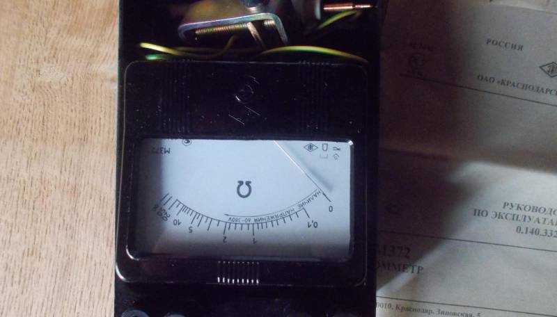
If it’s difficult to find, then we’ll do without it, the scheme will work just like that. If necessary, you can draw conclusions for connection and use a “tester” (avometer or multimeter - the same thing) during the search in resistance measurement mode. Almost everyone has this device.
Advice. A simple field-effect transistor with clamped terminals (drain and source) in the crocodiles on the avometer probes can serve as an “ersatz finder” for hidden wiring. The Avometer naturally works in resistance measurement mode.

Assembling the circuit

We assemble all the parts using a canopy using wires according to the diagram. We solder a piece of single-core wire 5-10 centimeters long onto the transistor gate. It will act as an antenna.
After assembly, you can pack everything into any suitable case, such as a plastic soap dish.

Looking for wiring
We bring the device turned on to the wall and begin to move the antenna along it. In the place where the live wire is located, a humming noise grows from the phone (like a working transformer). The closer to the wire, the stronger the sound will be.
You can more accurately find the wiring using the ohmmeter readings; when approached, it shows the least resistance. To work with an ohmmeter, turn off the power to the device.
How the device works
The whole point (as we have already said) is the high sensitivity of the field-effect transistor. The electromagnetic field induced on its gate with the antenna opens the transistor. Current is applied to the phone, and it begins to emit sound signals at a frequency of 50 Hertz (alternating current frequency).
An ohmmeter measures the resistance between source and drain. It becomes smaller as the gate signal increases.
Now let's look at more complex devices, without going too deep into the details.
On the chip
A very common hidden wiring finder circuit is based on the K561LA7 microcircuit.

Attention. The microcircuit may be designated without the letter “K” in front - this means that it is not general purpose, but special - of higher quality.
This is a digital chip with the simplest logic, but it works great as an amplifier.
Here is the circuit diagram itself with the pinout of the microcircuit:

The numbers on the diagram indicate the pin numbers.
In addition to the microcircuit itself, we also need an LED. This can be AL307 or its analogues (AL336) with any letter designation and any color, as well as a 3-15 V power supply.
Attention. If we choose a power supply greater than 3-5V, then the current through the LED must be limited by a series-connected resistor of 1-1.5 kOhm.


The principle of operation is simple - a signal from the antenna is supplied to the inputs, as in the previous case, it is amplified. The fact that there is voltage at the input is indicated by the lighting of the LED. Two logic elements (AND-NOT) are connected in series, because the outputs of the microcircuit are inverse, that is, if there is a signal at the input, then there is none at the output and vice versa.
The only disadvantage of this finder is that it does not determine the distance to the wire.
It can also be mounted with a canopy and placed in any convenient building.


Having examined simple circuits of hidden electrical wiring detectors, we will also describe the design for experienced radio amateurs.
Combined hidden wiring finder
This device is a “two-in-one” device that can operate both in electromagnetic radiation search mode and as a metal detector.
Here is his diagram:
The selection of modes is carried out by switch S 1, which can supply voltage to one or another unit; we will consider them in turn.
Metal detector unit
It is located in the upper part (currently disabled according to the diagram) and consists of the following nodes:
- Magnetic antenna on a ferrite rod (WA 1);

- A generator assembled on a KT315 transistor (VT 1) and a second magnetic antenna coil (L2);

- Receiver unit on the first coil of the magnetic antenna (L1), capacitor C2 with a detector on the KD522 diode (VD1);


- Amplifier on microcircuit 140UD12 (DA1);

- Indicator in the form of a KIPMO1B LED (others can be used instead, for example AL 307);
- A pulse generator lasting up to a second based on two logical elements of a digital microcircuit of the simplest logic 561LE5 (D1 1; D 1 2);
- An audio frequency generator on the two remaining elements of the microcircuit;
- Piezoceramic emitter ZP-1 (VA 1).

How does a metal detector circuit work?
- The generator is tuned to a frequency close to the receiver's transmission threshold. Trimmer resistors R2 and R6 are used for this.
Advice. To adjust the device during operation, it is even better to select R2 not as an adjuster, but as a variable one, with a knob displayed on the control panel of the device.
- If there is metal nearby, the settings of the generator and receiver circuits change, and the generator signal passes through the receiver's frequency filter.
- Additionally, the operational amplifier - comparator DA 1 has a response threshold compared to the voltage supplied from the divider across resistors R9, R10 to its second input. If this value is exceeded it starts working. The signal is amplified by the operational amplifier to a level sufficient to be perceived by the generator at D1, D2 as a logical unit and start it. The HL 1 LED is also connected to the output of the amplifier, which, when illuminated, indicates that wiring has been detected.
- The signal from the first generator periodically triggers the audio frequency generator on D3, D4. A piezoceramic emitter connected to the generator output emits an intermittent signal.
Magnetic field search block
To start it, you need to set switch S 1 to the second position. This knot is much simpler. It is assembled on a second operational amplifier DA 2.
An antenna is connected to its input, and a second HL 2 LED is installed at the output. If there is interference (signal) at the antenna, the amplifier will raise its level and light up the connected LED.
Device assembly
We won’t give advice here, as the assembly instructions are useless, the techniques are the same as for installing all radio-electronic devices. It is difficult to make it with a canopy; it is better to use a printed circuit board.
Radio amateurs themselves know how to do everything. But there is one caveat - for stable operation you need to separate the magnetic and conventional antennas as far as possible.

Sometimes, if you don’t have a hidden wiring finder or the time (desire) to assemble it, you can try to find it using other devices.
Let me give you a few examples:
- Let's not forget about Oersted's experiment, which discovered the relationship between magnetism and electricity. The scheme for searching for hidden wiring is as follows - we connect the load and, based on the maximum deviation of the arrow, we find the position of the wires. The main thing is that the current is significant, for example, the iron or vacuum cleaner is turned on.

- A radio tuned to the maximum wavelength can respond to the wiring. The method works especially effectively if there are sources of high-frequency interference in the network.

- An electrodynamic microphone connected to an amplifier; the most common electret microphones today do not operate in this way. You can also use the pickup of an electric guitar by first removing the strings from it. It is better to search using a “single-coil” (narrower, in one row) than using a “humbucker”, which has protection from external interference.


- If you still have a cassette, or even better, a reel-to-reel tape recorder or player, then you can remove their head by removing it and extending the wires and look for the wires, using it to turn on the device for playback.
Attention. The magnetic head must be connected with a shielded wire.


- Some people also try to search for wires using applications on their smartphone. But from personal experience I will say that the method does not work. I used the “Metal Detector” program, so she did not see the closely held wire to which a three-kilowatt motor was connected. Although maybe I'm wrong.

I hope that our article not only gave you the answer to what a hidden wiring finder circuit looks like, but also helped you assemble this device yourself. We are also glad if you understand why you need to know the location of the hidden wires. Make home repairs quickly and safely.
In this article we will talk about simple circuits of hidden wiring indicators on transistors and microcircuits.
A device such as a hidden wiring indicator becomes necessary when repairs are being carried out in a room, and where and how the electrical wiring is installed is unknown. The probability of breaking the wiring at this time becomes quite high and the law of meanness is triggered: the electric drill drill hits the wiring exactly, which in the best case leads to its breakage, and in the worst case – damage to the electric drill or electrical injury.
To detect hidden electrical wiring, in most cases, a simple device consisting of a field-effect transistor and a pointer ohmmeter is sufficient. The principle of operation of the device is based on the property of a field-effect transistor - to change its resistance under the influence of interference at the gate terminal. When searching for hidden wiring, the transistor body is moved along the wall and the location of the wiring is determined by the maximum deviation of the device arrow.
 A more advanced option is to use a field-effect transistor, a headphone and one or three batteries (see figure). Transistor VT1 - type KP103, KP303 with any letter index (in the latter, the housing terminal is connected to the gate terminal). The BF1 telephone is high-impedance, with a resistance of 1600...2200 Ohms. The polarity of connecting the GB1 battery does not matter.
When searching for hidden wiring, the transistor body is moved along the wall and the maximum sound volume with a frequency of 50 Hz (if it is electrical wiring) or radio broadcasts (radio broadcast network) is used to determine the location of the wires.
Indicators of hidden wiring on transistors
A relatively simple device made with three transistors will help determine the location of hidden electrical wiring in the walls of a room (see figure). A multivibrator is assembled on two bipolar transistors (VT1, VT3), and an electronic switch is assembled on a field-effect transistor (VT2).
 The operating principle of the hidden wiring indicator is based on the fact that an electric field is formed around the electrical wire, and the finder picks it up. If the SB1 switch button is pressed, but there is no electric field in the area of the WA1 antenna probe, or the hidden wiring indicator is located far from the network wires, the VT2 transistor is open, the multivibrator does not work, and the HL1 LED is off.
It is enough to bring the antenna probe of the hidden wiring indicator, connected to the gate circuit of the field-effect transistor, closer to the conductor with current or simply to the network wire, transistor VT2 will close, the shunting of the base circuit of transistor VT3 will stop and the multivibrator will start working. The LED will start flashing. By moving the antenna probe near the wall, it is easy to trace the route of network wires in it.
The field-effect transistor can be any other from the series indicated in the diagram, and bipolar transistors can be any from the KT312, KT315 series. All resistors - MLT-0.125, oxide capacitors - K50-16 or other small ones, LED - any of the AL307 series, power source - Corundum battery or rechargeable battery with a voltage of 6...9 V, push-button switch SB1 - KM-1 or similar.
The body of the Hidden Wiring Indicator can be a plastic pencil case for storing school counting sticks. The board is mounted in its upper compartment, and the battery is placed in the lower compartment. A switch and LED are attached to the side wall of the upper compartment, and an antenna probe is attached to the top wall. It is a conical plastic cap, inside of which there is a metal rod with a thread. The rod is attached to the body with nuts; from inside the body, a metal petal is placed on the rod, which is connected with a flexible mounting conductor to resistor R1 on the board. The antenna probe can be of a different design, for example, in the form of a loop from a piece of thick (5 mm) high-voltage wire used in a TV. The length of the segment is 80... 100 mm, its ends are passed through the holes in the upper compartment of the case and soldered to the corresponding point on the board.
The desired oscillation frequency of the multivibrator, and therefore the LED flash frequency, can be set by selecting resistors R3, R5 or capacitors C1, C2. To do this, you need to temporarily disconnect the source output of the field-effect transistor from resistors R3 and R4 and close the switch contacts.
 The wiring indicator can also be assembled according to a slightly different scheme using bipolar transistors of different structures - a generator is made on them. The field-effect transistor (VT2) still controls the operation of the generator when the antenna probe WA1 enters the electric field of the network wire.
Parts used: C1-5...10 µF, VT1-KT209 or KT361 with any index, VT2-KP103 any index, VT3-KT315, KT503, KT3102 with any index, R1 50K-1.2M, R2 150-560 Ohm. Antenna made of wire 80…100 mm.
Indicators of hidden wiring on microcircuits
 The circuit of the simplest indicator on a CMOS chip is shown in the figure.
Element DD1.1 is an electromagnetic radiation detector, and element DD1.2 is a signal repeater. When wiring is detected, the piezo emitter HA1 will operate at a network frequency of 50 Hz. A piece of copper wire 5...10 cm long serves as an antenna. The sensitivity of the detector depends on its length. If the length is more than 15 cm, this can lead to self-excitation of the circuit, so its length should not be abused.
Four A316 type galvanic cells connected in series can be used as a power source.
 The following figure shows a diagram of a more complex version of the indicator on a CMOS chip, which, in addition to sound, also has a light indication of the presence of electromagnetic radiation.
It is built on a DD1 chip of the K561LA7 type, and all its elements are used. The circuit consists of an electromagnetic radiation detector on element DD1.1, a low-frequency generator (operating frequency about 1 kHz) on elements DD1.2, DD1.3 and an inverter DD1.4, which controls the HL1 LED. The circuit does not need to be configured.
 The following indicator circuit consists of two components - an AC voltage amplifier, the basis of which is the micro-power operational amplifier DA1, and an audio frequency oscillation generator assembled on an inverting Schmitt trigger DD1.1 of the K561TL1 microcircuit, a frequency-setting circuit R7C2 and a piezo emitter BF1.
When the WA1 antenna is located close to the current-carrying wire of the power supply network, the pickup of the EMF at an industrial frequency of 50 Hz is amplified by the DA1 microcircuit, as a result of which the HL1 LED lights up. This same op-amp output voltage, pulsating at 50 Hz, drives the audio frequency oscillator.
The current consumed by the device microcircuits when powered from a 9 V source does not exceed 2 mA, and when the HL1 LED is turned on - 6...7 mA. The power source can be a 7 D-0.125 battery, “Korund” or a similar one made abroad.
Sometimes, especially when hidden wiring is located high, it is difficult to observe the glow of the HL1 indicator and an audible alarm is sufficient. In this case, the LED can be turned off, which will increase the efficiency of the device. All fixed resistors are MLT-0.125, adjusted resistor R2 is SPZ-38B type, capacitor C1 is K50-6. The WA1 antenna is a foil pad on a board measuring approximately 55x12 mm.
The circuit board of the hidden wiring indicator is placed in a housing made of dielectric material so that the antenna is in the head part and is as far as possible from the operator’s hand. On the front side of the case there is a power switch SA1, an LED HL1 and a sound emitter BF1. The initial sensitivity of the device is set with a trimming resistor R2. An error-free mounted device does not require adjustment.
There are also more complex hidden wiring indicators, but they are needed more by professionals rather than amateurs.


